54 • Sail Switches 026-1701 Rev 0 01-05-98
down position when there is airflow in the
duct.
2. Cut a rectangular hole 1 1/2 x 2 inches in the
location where the switch is to be mounted.
3. Remove the switch housing so that the chas-
sis is exposed.
4. Use the chassis as a template to mark the two
mounting hole locations at the top left and
bottom right of the chassis.
5. Center punch and tap the holes where the
chassis is to be mounted. Use sheet metal
screw to attach the switch.
S437A
1. The S437A can only relay one state. Wire the
switch so that one wire connects to both the A
and B terminals (Figure 42). Run each wire to
an available point on a CPC input board.
2. Replace the switch housing
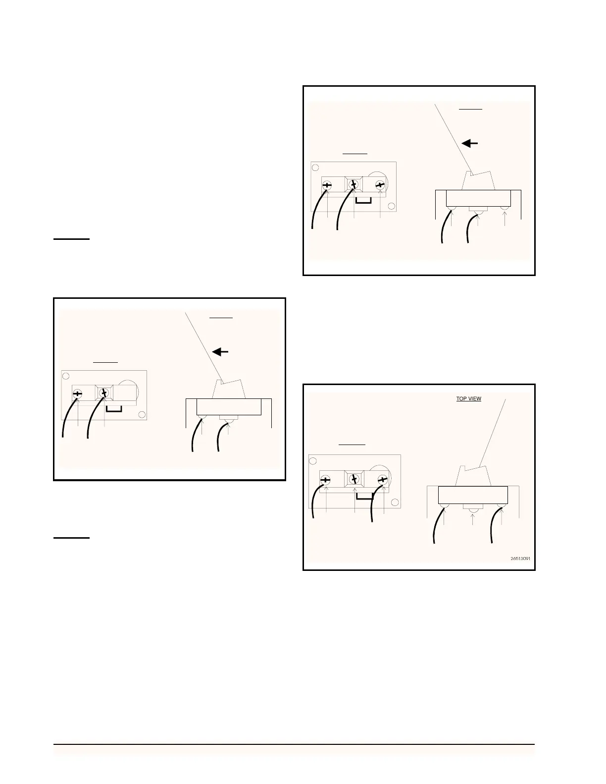
S637A
1. To wire the sail switch so that it sends a signal
to an input board when the sail is in the closed
position, connect a wire to both the A and B
terminals (Figure 43). Run each wire to an
available point on a CPC input board.
2. To wire the sail switch so that it sends a signal
to an input board when the sail is in the open
position, connect a wire to both the A and C
terminals (Figure 44). Run each wire to an
available point on a CPC input board.
3. Replace the switch housing.
Figure 42-S437A Switch Connection for Signaling When Airflow
is Present
S437A
A
B
A
B
AIRFLOW
SIGNAL TO INPUT BOARD WHEN SAIL IS CLOSED
CLOSED
OPEN
26513092
TOP VIEW
SIDE VIEW
Figure 43-S637A Switch Connection for Signaling When Airflow
is Present
Figure 44-S637A Switch Connection for Signaling No Airflow
S637A
A
B
C
A
C
SIGNAL TO INPUT BOARD WHEN SAIL IS CLOSED
CLOSED
OPEN
26513090
TOP VIEW
SIDE VIEW
S637A
A
B
C
NO AIRFLOW
IN DUCT
SIGNAL TO INPUT BOARD WHEN SAIL IS OPEN
CLOSED
OPEN
C
SIDE VIEW