Peripherals Manual 485 Alarm Panel • 5
Baud Rate
Rockers 6 and 7 on switch SW2 on the 485 Alarm Panel
determines the baud rate at which alarm messages will be
received across the COM B network. The 485 Alarm Panel
can only communicate at 4800 baud; therefore, both
switches 6 and 7 must be set to the DOWN position as
shown in Figure 4.
Printer Setup
The 25-pin female socket located at the bottom of the
485 Alarm Panel (labelled DB25S) may be used to connect
a printer. Connecting a printer will allow the 485 Alarm
Panel to dump alarms to the printer in ASCII format.
To connect a printer:
1. Connect the printer’s communication cable to
DB25S.
2. Locate the Mode switch on the 485 Alarm
Panel board (labelled SW3). Switch rocker
#1 on SW3 to the UP (ON) position as shown
in Figure 4.
Audible Annunciation
The 485 Alarm Panel comes equipped with a buzzer
that can be configured to sound when an alarm is present on
the controller. To enable this buzzer, locate the Mode
switch on the 485 Alarm Panel board (labelled SW3).
Switch rocker #2 on SW3 to the DOWN position as shown
in Figure 4.
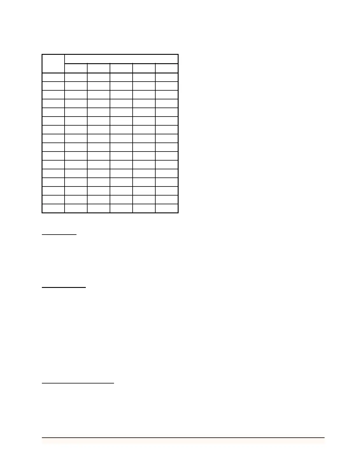
ID ROCKER POSITION
12345
1 UPDNDNDNDN
2 DNUPDNDNDN
3 UPUPDNDNDN
4 DNDNUPDNDN
5 UPDNUPDNDN
6 DNUPUPDNDN
7 UPUPUPDNDN
8 DNDNDNUPDN
9 UPDNDNUP DN
10 DN UP DN UP DN
11 UP UP DN UP DN
12 DN DN UP UP DN
13 UP DN UP UP DN
14 DN UP UP UP DN
15 UP UP UP UP DN
16 DN DN DN DN UP
Table 1 - 485 Alarm Panel Dip Switch Settings