Peripherals Manual Refrigerant Level Transducer Probe (P/N 207-1000) • 45
Refrigerant Level Transducer Probe (P/N 207-1000)
Overview
Refrigerant level transducer (RLT) probes are used for
the monitoring of refrigerant levels in vertical and horizon-
tal tanks. RLT probes are designed to be inserted directly
into a receiver tank and require no calibration.
RLT probes will fit a standard 3/4” MPT connection
and are suitable for use with R22, R134A, and other ap-
proved refrigerants. The temperature of the refrigerant be-
ing monitored can range from 50° F to 150° F.
The RLT probe must be ordered with the correct im-
mersion length for your receiver. Contact CPC for assis-
tance.
Installation
1. Install RLT probe according to tank manu-
facturer’s specifications.
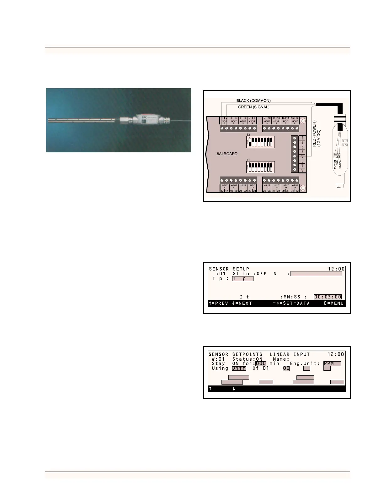
2. Connect the Black (Common) to an available
odd numbered terminal on the 16AI board.
3. Connect the Green (Signal) wire to an avail-
able even numbered terminal on the 16AI
board. The odd and even numbered terminals
must belong to the same point on the 16AI.
4. Connect the Red (Power) wire to an available
12 V power supply terminal on the 16AI
board.
5. Set the dip switch that corresponds to the
point where the RLT probe is connected to
the “off” (down) position. Figure 35 shows
the RLT probe completely wired.
Software Setup
1. After you have assigned the board and point
number in the RMCC for the RLT probe, go
to Sensor Setup and select the sensor number
of the RLT probe. In the type field, scroll
through the options until Linear appears.
2. Select “Setpoints” from the Sensor Control
menu. Select the appropriate sensor for setup.
Enter the gain as 20 and offset as 0.
3. Set the alarms for the sensor. To do this, se-
lect “Alarms” from the Sensor Control menu.
Select the sensor you want to set the alarms
for. It is recommended that the RLT’s Low
Alarm set point be set to 10 (10%) and the de-
lay be set to 30 minutes.
Figure 35-Wiring Diagram for RLT Probe
=PREV =NEXT ->=SET-DATA 0=MENU
SENSOR SETUP 12:00
:01 St tu :OFF N :
Tp: T p
I t :MM:SS : 00:03:00
SENSOR SETPOINTS LINEAR INPUT 12:00
#:01 Status:ON Name:
Stay ON for:000 min Eng.Unit: PPM
Using Diff Of 01 00 00 00
0 Of 0 0 0 0
Gain 0 Offset 00000 mV
ON: 0 Dly: 0000 OFF:0 Dly:0000
=PREV =NEXT ->=SET 0=MENU