Peripherals Manual Refrigerant Transducer (P/N 809-1550) • 29
5. Cut off the shield at the transducer and
ground at either a ground lug or an odd termi-
nal on the 16AI board.
6. Set the corresponding 16AI Input Type Dip
Switch to the DOWN position, as shown in
Figure 24.
Multiple Refrigerant Transducers Layout
Connect the refrigerant transducers to the 16AI input
board and power supply as shown in Figure 25.
1. Attach the black wire to the -V terminal of
each of the RTs and the 0V terminal to the
power supply.
2. Attach the green wire to the 0V terminal of
each of the RTs and an odd terminal on the
16AI input connections.
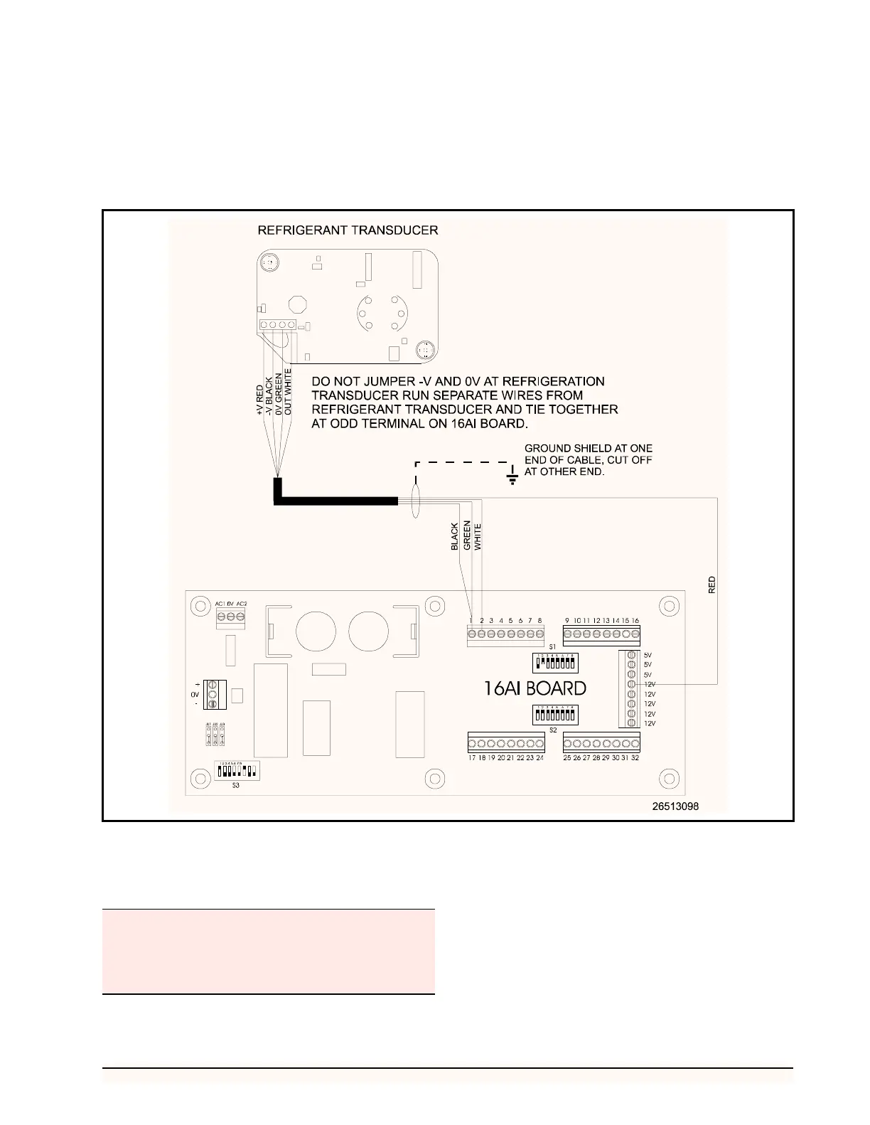
Figure 24 - Single Refrigerant Transducer Layout
A maximum of sixteen RTs may be connected to one
power supply.
Do NOT jumper the -V and 0V terminals of the refrig-
erant transducer.