54
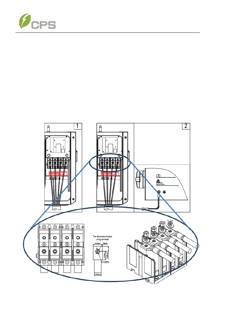
2. Grounding/Bonding. The inverter provides 1 grounding connection
on the AC side and one bonding location. These configurations are
illustrated below Figure 3-29).
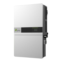
(a) Grounding via the ground busbar (left) [1] This is required for
grounding the equipment by running the EGC with the
ungrounded conductors.
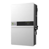
(b) Bonding via the external grounding point (right) [2]. The external
bonding connection is provided in case the inverter/mount needs
to be bonded to a metallic structure on which it may be mounted.
Figure 3-29 AC Output and Ground Cable Connection



 To Next Page