37
Operation
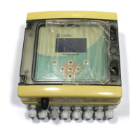
Figure 18 Chlorine channel (galvanic)
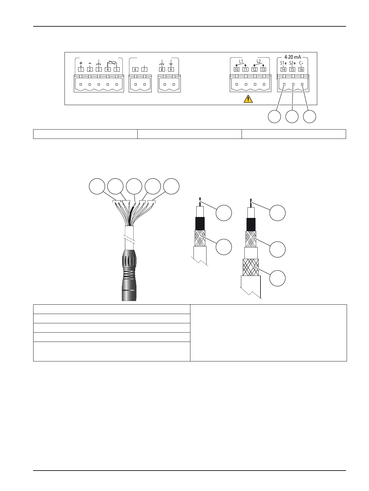
For Chlorine galvanic electrode connection (code 53 59) refer to Figure 19.
Figure 19 Chlorine galvanic electrode connection
Sensor installation
The correct functioning of Chlorine galvanic sensor, code 53 59, is ensured when the
sensor is installed as indicated in Figure 20.
Important notes:
• The sensor is supplied with some mL of alcohol and water inside. This improves the
electrode’s response.
• Remove the joints caps avoiding the leakage of the liquid.
• Inside the chamber there are 50 glass pearls. If the sensor is dismounted, pay
attention, do not lose them.
1 Chlorine 2 Temperature 3 Common
Relays
Cl
2
Galvanic Cell mV Electrode
Signal
1 2 3
1 Gray and red cable: To terminal 1 Connections for Redox (mV) sensor:
6 Coaxial cable: To terminal 7
7 Coaxial cable: To terminal 8
8 Triaxial cable: To terminal 7
9 Triaxial cable: To terminal 8
10 Triaxial cable: To terminal 9
2 Green and blue cable: To terminal 2
3 Black cable: To terminal 3
4 White and brown cable: To terminal 4
5 Pink and Yellow cable: To terminal 5