Vortex
22
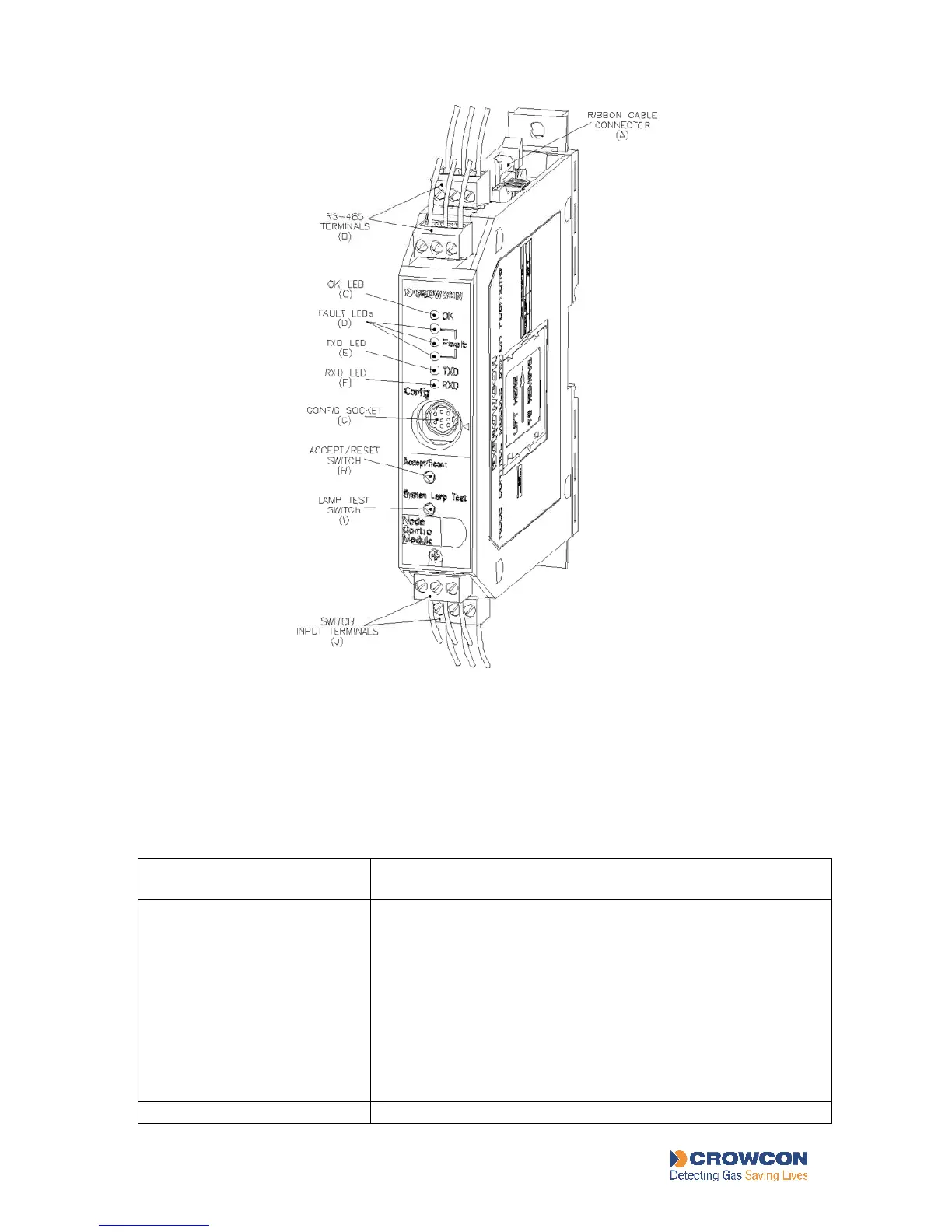
Figure 3: Node Contr oller Module
4.2.2 Node Controller Module indicators, switches and connectors
Table 6: Node Controller Module indicators, switches and connectors
Letters refer to labels in Figure 3.
Ribbon cable socket
: see
wiring diagram,
Figure 17
These ports are intended for use by personal
computers, programmable logic controllers and distributed
control systems to allow remote monitoring of the system. It
uses the Modbus RTU Slave protocol running at 9600 baud
(address map available on application).
There are two connectors to simplify "daisy-chaining" of
multiple systems (up to 32 Vortex systems) which are
electrically connected together. The Vortex at the end of a
Modbus chain can use this second connector to attach a
terminator (120 Ohm).
OK LED