Vortex
43
V
RTEX TECHNICAL
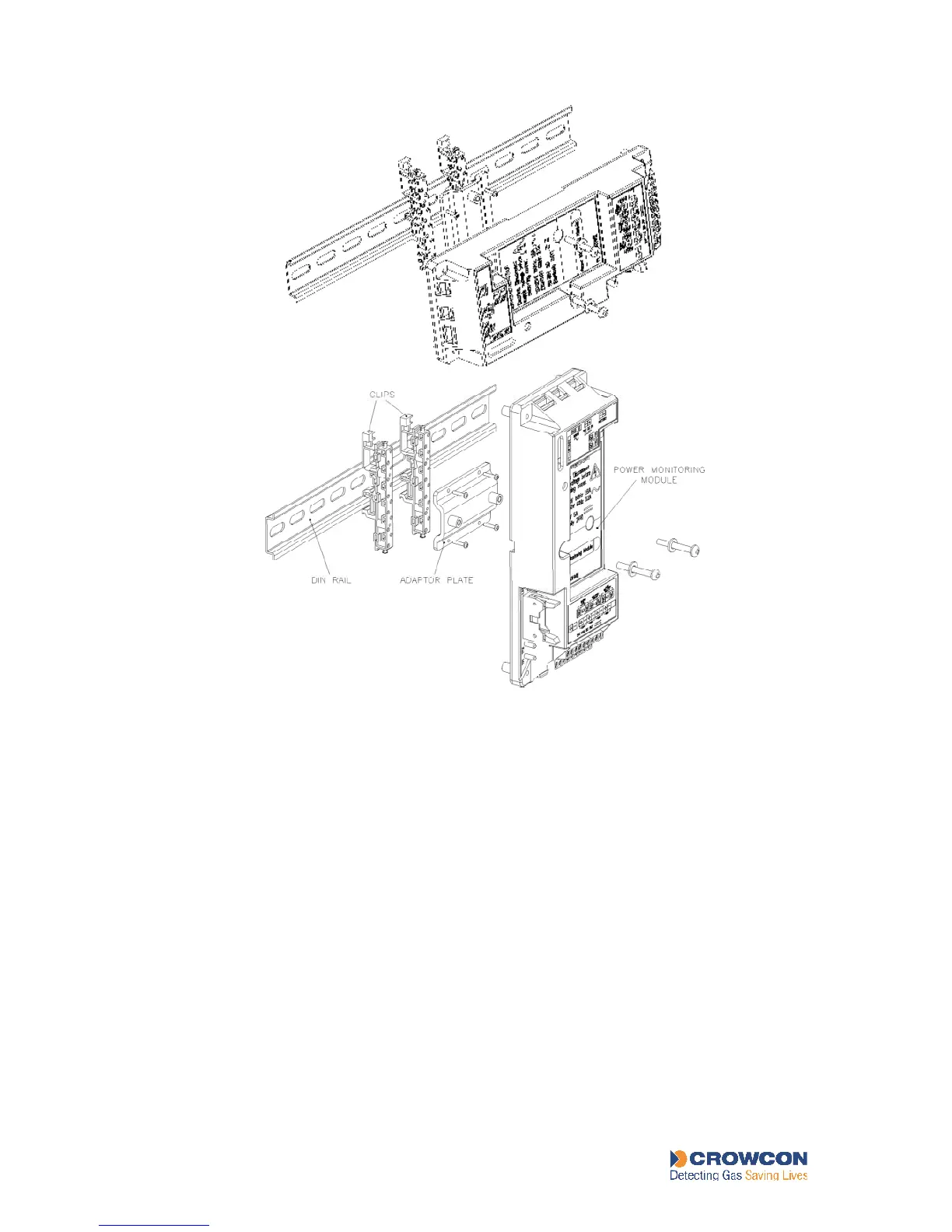
Figure 12: Alternative mountings for the Power Monitoring Module
4.7.4 Backup batteries
The Power Monitoring Module is capable of charging and monitoring two 12V, 2Ah at
0.25A, sealed lead-acid batteries connected in series to provide 24V dc. If the main ac power
supply is lost, the system automatically switches over to the standby battery operation, this is
indicated on the Power Status LED on the Display Module. If loss of power continues, the
battery is disconnected from the system to prevent it from being over-discharged and
permanently damaged.
In the Vortex standard enclosure these batteries are mounted behind the Power Monitoring
Module. There is a 10A in-line fuse between the two batteries behind the Power Monitoring
Module. For instructions on changing these batteries, see section 7.9.
Larger batteries or external backup power supply systems may be supplied and fitted
according to requirements, details of these are beyond the scope of this manual. See the
Specification Sheet supplied with the system for more information.
NOTE Where external DC supplies are used, they should be connected via the DC input
connection NOT the battery input.