Vortex
36
VORTEX TECHNICAL
Table 14: Relay Logic configurable properties
Property Configuration
Detector link event (8
per detector)
Each detector link event can be one of seven
events: Alarm 1, Alarm 2, Alarm 3, Inhibit,
Fault, High Information, Low Information
(when configured as such for the High and
Low regions of a 4-20mA detector)
System links (8 for system fault and 8 for
system sounder)
The system fault event and system sounder
event can be linked to a relay
Relay Vote count The Vote Count for the
relay, this is the number of the specified
events (detector events and system events)
that must occur to trigger the relay.
For example, if three detector events have
been selected for the relay, a vote count of 1
means that any of the events will trigger the
relay.
Fire detectors will generate Alarms 1, 2, and 3 on a fire event.
In Vortex PC, for each relay, select the detector(s) and the corresponding events, or system
properties to trigger the relay.
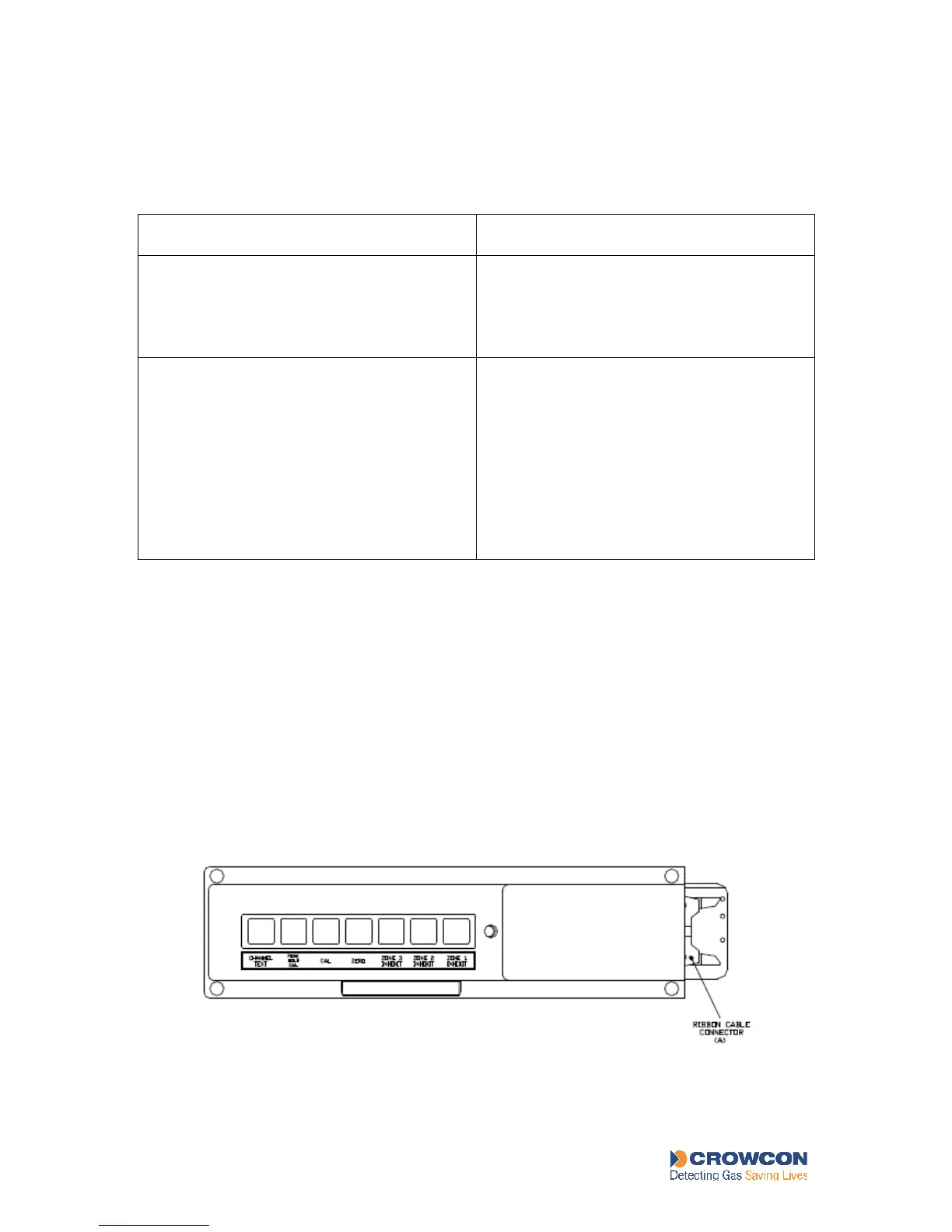
4.6 The Display Module
4.6.1 Functions of the Display Module
Vortex, Vortex Rack and Vortex Panel include a Display Module that in normal operation
provides a display of detector input and reports the current status of the system. It also
provides local user control of the system through a set of push-buttons, seven at the back and
five on the front. See Figure 9 and Figure 10.
Figure 9: Back of Display Module