Vortex
9
2 SYSTEM OVERVIEW
2.1 General
This chapter gives an overview of the Vortex system, its modules and their interconnection.
Vortex can be supplied in a number of variations depending on the modules and enclosures
required.
If you simply use Vortex for monitoring and responding to alarms, it is not necessary to read
this chapter. See chapter 6, Operation.
In all other cases, we recommend that you read this section.
2.2 System description
2.2.1 System modules and options
The basic parts of the Vortex system are listed in Table 3. Some are optional. The essential
components are marked with an asterisk (*).
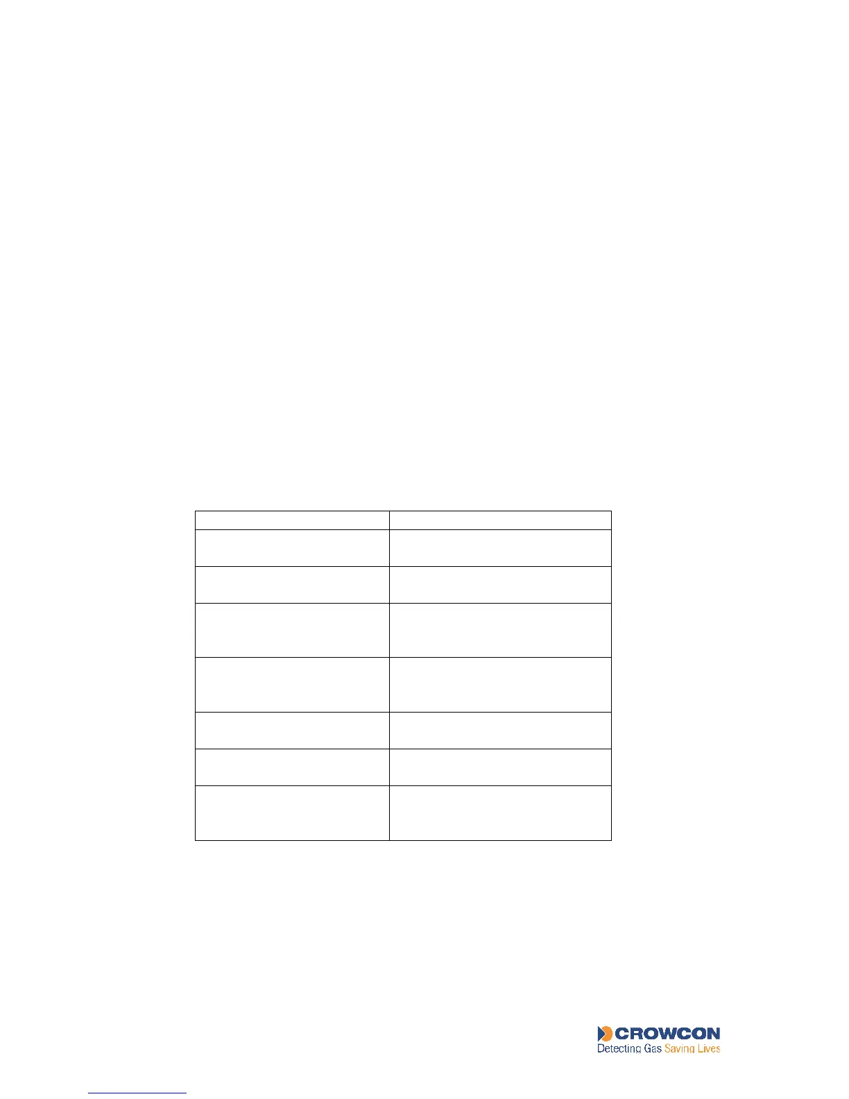
Table 3: List of Vortex modules
Module Description
*Node Controller Module Central control module of
system between modules.
.*Bus Rail Electrical connections and
communications Modules
*Quad Channel Input Control and measurement
of input, up to 4channels per
module, maximum 3 modules.
Relay Output Module Control of output, up to 8
channels per module, maximum
4 modules.
Display Module User display and limited
configuration
.*Power Monitoring. unit Control and protection of power
supply
Module Mains power
supply
If the Mains Power Supply Unit
is omitted, a suitable dc power
supply must be provided.
Figure 1 shows the general assembly of the modules within the Vortex system. The number
and arrangement of the modules will vary depending on your Vortex system configuration.