Vortex
51
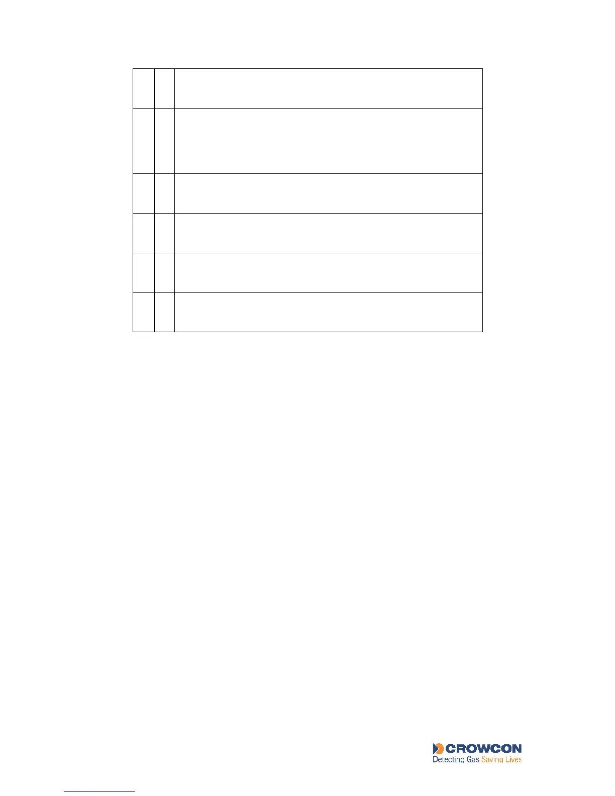
○
●
○
2 FRAM data integrity fault.
Node Controller Module problem. Contact Crowcon.
○
●
●
3 Internal bus fault.
Problem with the Ribbon Cable between the Display Module,
Node Controller and the Power Monitoring Module. Check the
Ribbon Cable is connected and intact. If persists contact
Crowcon.
●
○
○
4 Display access fault.
Check the connection between the Node Controller Module and
the Display Module. If persists contact Crowcon.
●
○
●
5 Power Monitoring Module access fault.
Check the connection between the Node Controller Module and
the Power Monitoring Module. If persists contact Crowcon.
●
●
○
6 External bus fault.
Ensure all modules are located on the Bus Rail correctly. If the
fault persists contact Crowcon.
●
●
●
7
Relay Module fault.
Relay Coil failure or access fault. Check all Relay Module
address switches are correct. If persists contact Crowcon.
MAINTENANCE
7 MAINTENANCE
7.1 Detector Functional Testing
Crowcon recommends that you check detectors routinely to ensure correct calibration and
operation.
For gas detectors, heads require recalibration at least every 6 months. Fire detectors should be
tested every 3 to 6 months. Site procedures may require more frequent testing.
For detailed instructions on the routine functional testing of detectors, please refer to the
relevant Installation, Operating and Maintenance Instructions provided with each detector.
7.2 Inhibiting input
During calibration (sections 3.8 and 7.3) or Channel Test (section 7.4), it is often necessary to
inhibit the inputs so that relays are not tripped.
Using the Display Module, a zone (a group of four channels on a Quad Channel Input
Module) can be inhibited by pressing the appropriate ZONE INHIBIT button on the back of
the Display Module. To return the zone to normal operation, press the ZONE INHIBIT
button again.
Using VortexPC, you can inhibit individual channels. See VortexPC Help.