Vortex
31
VORTEX TECHNICAL
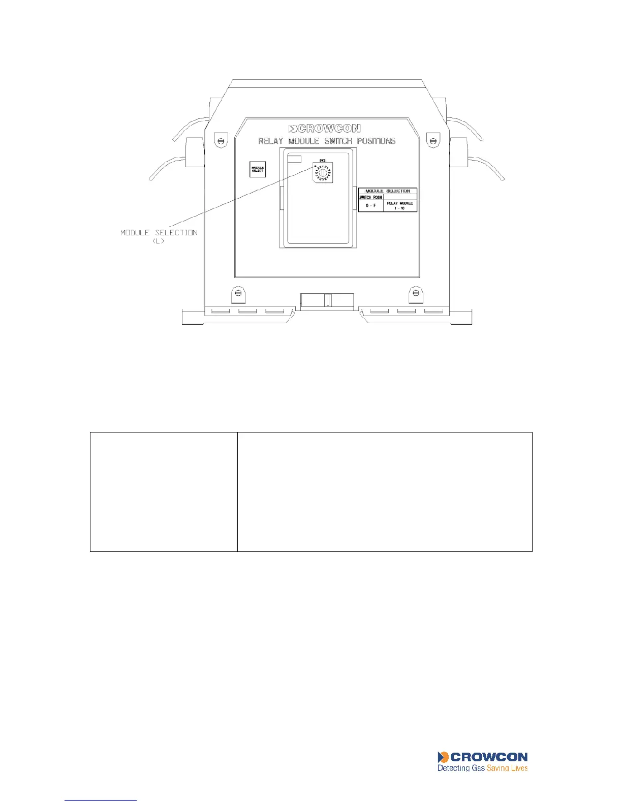
Figure 8: Relay Ouput Module Selection Switch
Table 11: Relay Output Module switch settings
The letters refer to labels in Figure 8
Module Selection
Switch (L)
Determines whether the relays on the module are configured
as relays1-8, 9-16, 17-24 or 25-32..
Position 0 - This module has relays 1-8
Position 1 - This module has relays 9-16 if two, three or four
modules are used
Position 2 - This module has relays 17-24 if three or four
modules are used
Position 3 - This module has relays 25-32 if four modules are
used
Relay Output Modules are configured in VortexPC, using the Outputs Configuration option
on the Vortex menu. Select the appropriate relay to view its current configuration. The
configurable properties of relays are listed in Table 12.