Vortex
46
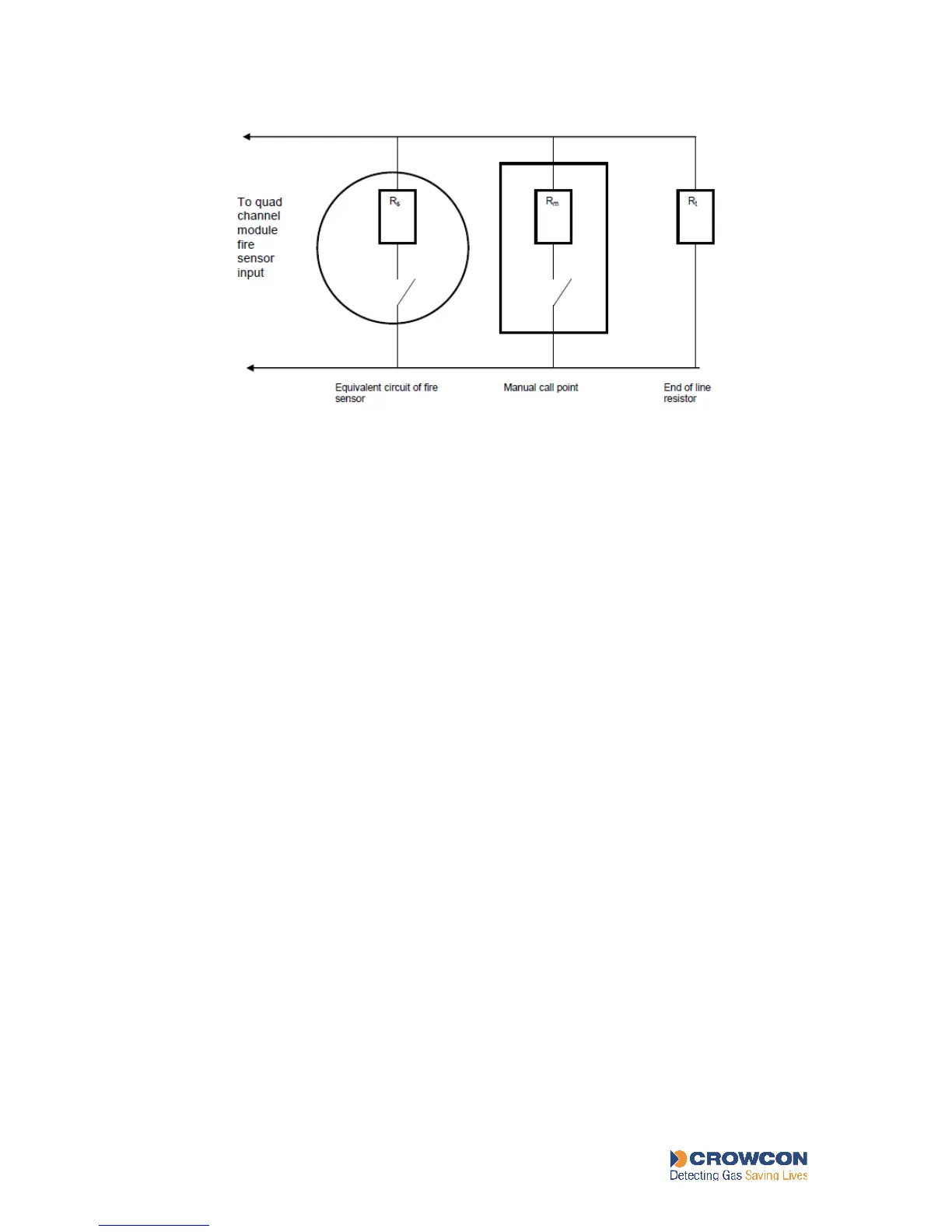
Figure 13: Representation of a fire detection circuit
With no detectors in alarm (all switches open) a small current flows in the circuit through the
end-of line resistor (Rt). If a short circuit or open circuit cable fault occurs, the current in the
loop increases or decreases. The Quad Channel Input Module detects this and a fault alarm is
raised.
FIELD DEVICES
If a fire is detected (either the fire detector switch closes or the call point is activated), the
current flowing in the loop changes and the Quad Channel Input Module detects this and a
fire alarm is raised.
Figure 18 in Appendix B shows the electrical connections to be made to the Quad Channel
Input Module. For essential information about earthing, see Appendix F.
5.3.1 Fire detector location
It is beyond the scope of this manual to describe the rules and regulations governing the
installation of fire detection equipment. Assistance and guidance should be sort from the
governing body in the country concerned before fire detection equipment is installed.
Further advice is available from Crowcon if required.
5.4 Connections for audible/visual alarms
Vortex is able to drive audible and visual alarms via any relay outputs. Any 20 – 29.5V dc
field device (to a maximum of 500mA) may be powered by the dedicated dc outputs on the
Power Monitoring Module.
For essential information about earthing, see Appendix F. For further assistance, please
contact Crowcon.
RATION