The Modbus address of the Vortex on the system. Usually 1
unless the system is multi-drop.
Number of Quad Channel
Input Modules
1, 2 or 3
Number of Relay Output
Modules
0, 1, 2, 3 or 4
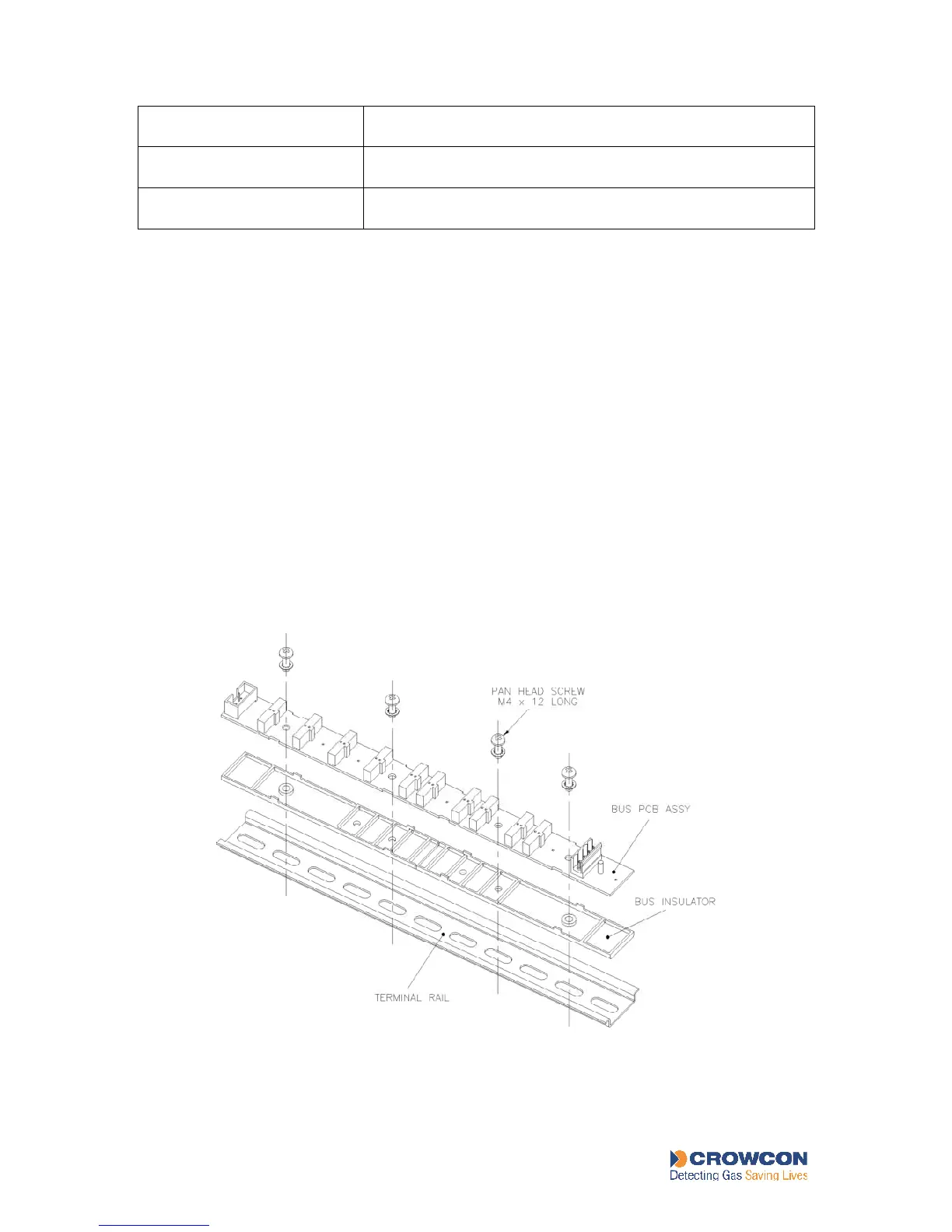
4.3 The Bus Rail and electrical connections
The Vortex modules (apart from the Display Module and the power supply components) are
mounted on a bus PCB, which acts as a motherboard providing the necessary power and
communications to the modules, see Figure 4: Bus Rail Assembly Details. The bus PCB is
inserted into a DIN Rail to create the Bus Rail assembly.
The Node Controller Module, Quad Channel Input Modules and Relay Output Modules have
plugs that slot into sockets on the bus PCB, and clips to lock them on to the DIN Rail. Figure
1 shows how the modules are arranged on the Bus Rail assembly. For instructions for
mounting the modules and removing them from the rail, see section 7.8.
The Bus Rail accepts DC power from the Power Monitoring Module through a 2-way cable
attached to terminal JP1 on the bus. JP1 pin 1 is the positive connection.
Two Bus Rails can be connected together within the same cabinet, using the 10-way Bus
Interconnection Ribbon Cable Assembly. Using two Bus Rails allows the maximum number
of modules in one Vortex system to be fitted. The Vortex standard enclosure holds only one
Bus Rail.
Figure 4: Bus Rail Assembly Details