64 A255 Robot Arm User Guide
99-04-23
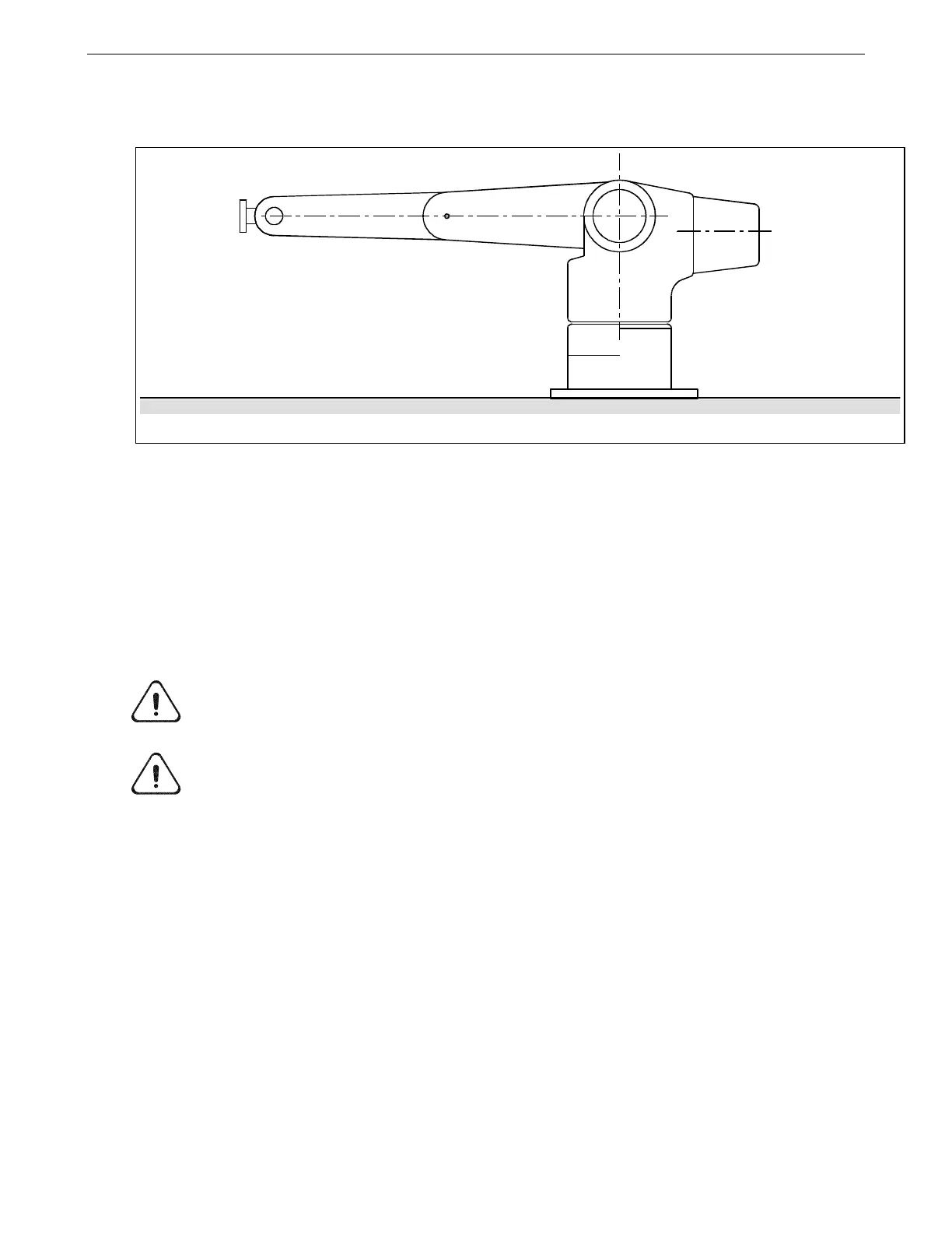
3. Use the teach pendant to move the arm into an approximate Zero position,
refer to the drawing below.
4. Transfer control of the robot from the teach pendant to the terminal.
a. At the teach pendant, press ESC until the Terminate To screen appears.
b. Select F1 (yes), to terminate to the host point of control.
5. Run the Robcomm3 Terminal Emulator.
2) Adjust All the Joints in Sequence to the Zero (calrdy) Position
Adjust joints 1, 2, 3, 4, and 5, to their Zero position using the following sequence.
Use the following figure as a reference.
Caution! Review the safety precautions at the front of this guide before entering
within the robot’s work envelope, refer to page 24.
Warning! Have someone else available to strike the e-stop when working inside the
robot envelope. Working within the robot envelope when arm power is on represents a
risk. In the case of a controller or arm failure, there is a danger of impact or trapping.
Joint 1
1. Type limp 1 and press Enter, the waist joint limps.
2. Type w1 and press Enter to display the position of the robot joints in motor
pulses. The first number lists the position of axis 1.
3. By hand, rotate axis 1 until it is positioned against one of its hardstops. Do not
compress the hardstop.
4. Press Ctrl+E to terminate the w1 command.
5. Type /diag/xzero 1 and press Enter to zero the joint 1 position registers.
6. Type w1 and press Enter and then rotate axis 1 until it is against its other
hardstop.
7. Type speed 10 and press Enter.
Arm posed in the Zero (calrdy) position