Chapter 8: Calibration 65
99-04-23
8. Type nolimp and press Enter. Joint 1 unlimps.
9. Note the displayed motor pulse position and divide the travel value by two. This
determines the value of the half-way position.
Note: The sign (±) must be opposite of the displayed value.
10. Type motor 1, <±
±±
± half-way position value> and press Enter. The arm moves to
the half-way position.
11. Type /diag/xzero 1 to set the Zero position for joint 1. The motor pulse count
for joint 1 (W1) should now read zero.
Joint 2
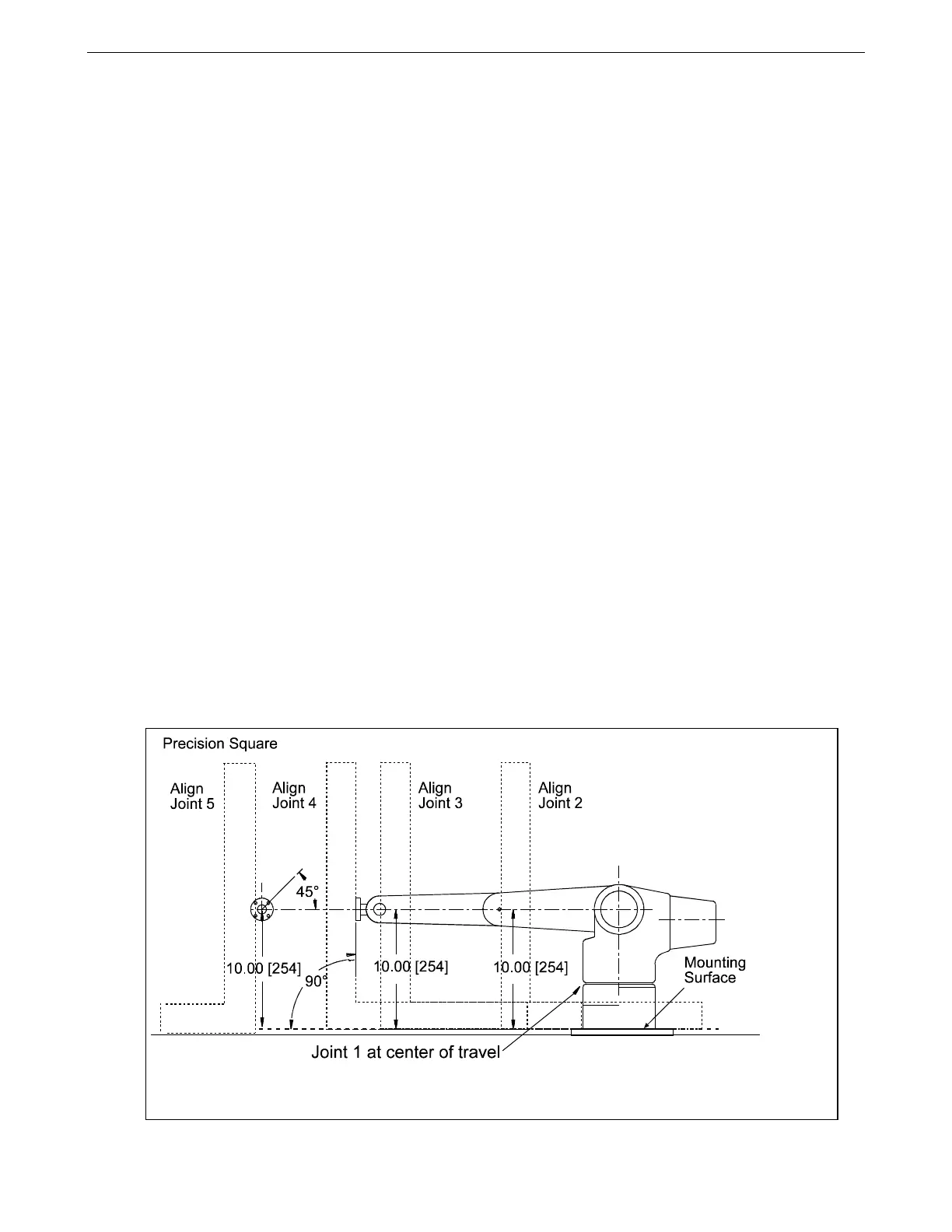
1. Place the 24-inch square to measure the perpendicular distance from the
robot’s mounting surface to the joint 3 axle hole on the side of the arm (refer to
the drawing on the previous page).
2. Use the motor command to adjust the joint so the measured distance is ten
inches. For example:
Type motor 2, <±
±±
± motor pulse counts> and press Enter.
Note: Use small increments of motor pulses to move the arm
(20 pulses).
Joint 3
1. Place the 24-inch square to measure the perpendicular distance from the
robot’s mounting surface to the joint 4 axle hole on the side of the arm (refer to
the drawing on page 64).
2. Use the motor command to adjust the joint so the measured distance is ten
inches. For example:
Type motor 3, <±
±±
± motor pulse counts> and press Enter.
The Zero (calrdy) position for the arm. Use a 24-inch precision square with scale to pose joints 2, 3,
4, and 5.