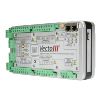
Figure 5: Right-hand view of the Vecto III device
Figure 5 shows the USB port located on the right-hand side of the device.
2.4.2 Vecto III User Interface
Figure 6: User Interface
Information LEDs on the top-left front side of the device provide status information.
The interpretation of the status LEDs is discussed in Section 3.2. Two buttons located
below the LEDs are used to control the power state of the device. The Power button is
recessed to avoid accidental switching. It rests flush with the surface plate in the off-
state and sits below the surface plate in the on-state. The On/Off button is a push-
button that returns to the non-pressed state when released. The use of the buttons is
discussed in Chapter 3.
2.4.3 Power Supply
The Vecto III can be powered and charged directly from mains (90 – 300 V AC/DC) via
a power factor corrected internal power supply.
The Vecto III can also be powered and charged via an IEEE 802.3-2008 compliant Power
over Ethernet (PoE) power supply.
 Loading...