EasyManuals Logo

CT Lab Vecto III User Manual

CT Lab Vecto III
80 pages
To Next Page IconTo Next Page
To Previous Page IconTo Previous Page
Page #41 background imageLoading...
Page #41 background image
Vecto III User Manual
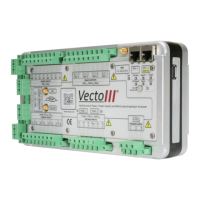
2.4.8 Digital inputs
The inputs are arranged into two clusters (1 kV isolation); each containing two digital
inputs (300 V
DC
max) and a 5 V power source with a common. These inputs can be used
to attain information like breaker position or disturbance information that can be
added to the PQ events/data. The inputs are available on an 8-terminal lockable
connector plug with screw terminals. Each terminal can accommodate conductors
with size up to 2.5mm
2
.
Figure 14: Digital inputs connection layout
Terminal
Legend
Description
1.
IN1
Input 1
2.
IN2
Input 2
3.
+5 V
Input A 5 V Supply
4.
CM
Input A - Common
5.
IN3
Input 3
6.
IN4
Input 4
7.
+5 V
Input B 5 V Supply
8.
CM
Switch B - Common
Table 6: Digital inputs connection layout

Table of Contents

Questions and Answers:

Question and Answer IconNeed help?

Do you have a question about the CT Lab Vecto III and is the answer not in the manual?

CT Lab Vecto III Specifications

General IconGeneral
BrandCT Lab
ModelVecto III
CategoryMeasuring Instruments
LanguageEnglish