EasyManuals Logo

CT Lab Vecto III User Manual

CT Lab Vecto III
80 pages
To Next Page IconTo Next Page
To Previous Page IconTo Previous Page
Page #40 background imageLoading...
Page #40 background image
Vecto III User Manual
2.4.7 Relay Outputs
Four digital relay outputs (100 mA
AC-RMS
, 350 V
AC-RMS
) are used to provide digital output
information or to control external processes. The outputs are arranged into 2
galvanically isolated clusters (1 kV isolation); each containing a switch contact. The
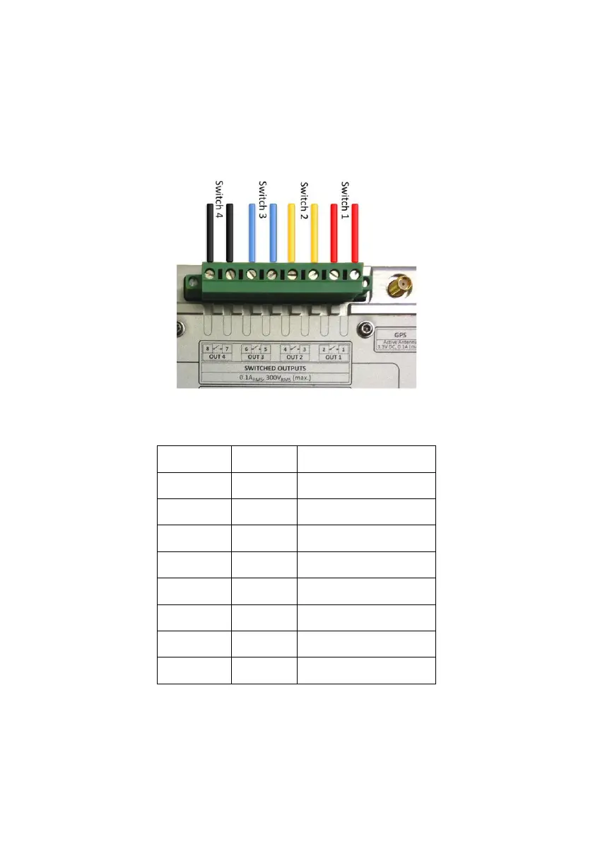
relay outputs are on an 8-terminal lockable connector plug with screw terminals. Each
terminal can accommodate conductors with size up to 2.5 mm
2
.
Figure 13: Relay switch connection layout
Terminal
Legend
Description
1.
OUT1
1
Switch 1
2.
OUT1
2
Switch 1
3.
OUT2
1
Switch 2
4.
OUT2
2
Switch 2
5.
OUT3
1
Switch 3
6.
OUT3
2
Switch 3
7.
OUT4
1
Switch 4
8.
OUT4
2
Switch 4
Table 5: Relay switched outputs layout

Table of Contents

Questions and Answers:

Question and Answer IconNeed help?

Do you have a question about the CT Lab Vecto III and is the answer not in the manual?

CT Lab Vecto III Specifications

General IconGeneral
BrandCT Lab
ModelVecto III
CategoryMeasuring Instruments
LanguageEnglish