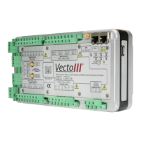
Table 2: Voltage connection layout
Input voltages can be up to 600 V
AC-RMS
. The 20 mV resolution results in accurate
recording of all harmonic components up to the 63
rd
harmonic component.
A high impedance input prevents the accidental shorting of VT inputs to system ground
and also eliminates ground loops.
Differential resistive inputs assure a safe and stable analog input stage with minimal
phase error, a high bandwidth and zero temperature drift.
2.4.5 Current Inputs
The Vecto III has 4 galvanically isolated resistive current shunt inputs with input
impedance of 20 m and a full-scale measurement range of 6 A
AC-RMS
.
Resistive shunts provide excellent AC and DC response; zero offset drift and very low
temperature drift.
The 3-second overcurrent withstand rating of each input is 50 A. The galvanic isolation
voltage between each channel and earth is 1 kV.
The current inputs are by an 8-terminal lockable connector plug with screw terminals.
Each terminal can accommodate conductors with size up to 2.5 mm
2
.

 Loading...