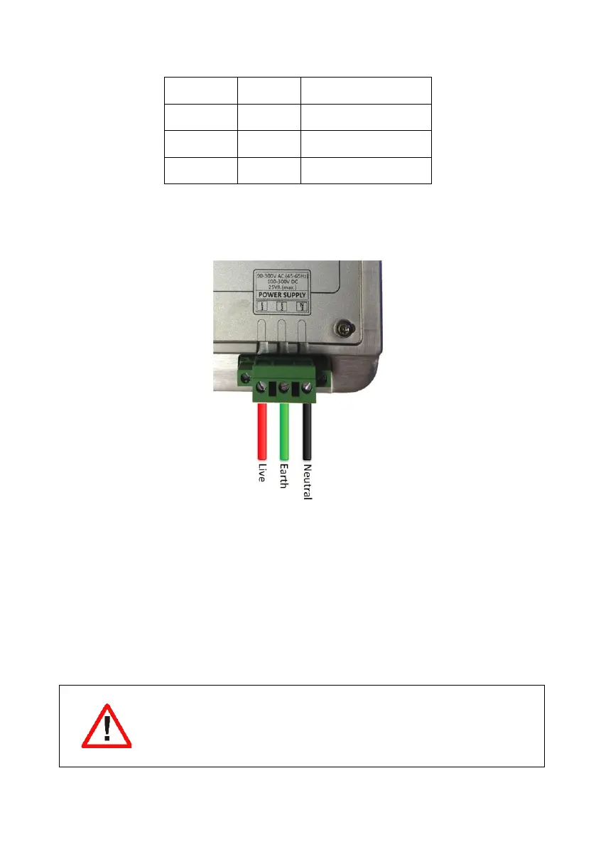
Home
CT Lab
Measuring Instruments
Vecto III
CT Lab Vecto III User Manual
4
of 1
of 1 rating
80 pages
Give review
Manual
Specs
To Next Page
To Next Page
To Previous Page
To Previous Page
Loading...
Vecto
II
I
User Manual
55
Terminal
Legend
Description
1.
L
Live Termin
al
2.
E
Safety Earth
3.
N
Neutral Terminal
Table 8: AC power c
onnection layout
Figure
27
:
Vecto III AC p
ower supply con
nection
4.2.2
Power Over E
thernet
In addition to, or a
s alternative to AC
power, the device can be powered via any of the
Ethernet ports
using an
IEEE 802.3-2008 compliant po
wer source
(48
V)
.
4.2.3
Voltage connection
s
4.2.3.1
S
ingle phase connection
Always connect th
e safety ear
th terminal located
on the power
connector first
54
56
Table of Contents
Table of Contents
2
Safety Instructions
8
Symbols
8
Safety Standards Compliance
9
General Safety Information
9
How to Mitigate Risks
11
Always Earth the Device First
11
Install External Shorting Blocks
11
Locking of Terminal Plugs
11
Use of External Fuses or Circuit Breakers
11
Provide Surge Arrestors
11
Statements and Notices
12
Statement of Reliability
12
Proprietary Rights
12
Copyright
12
Trademarks
12
Figure 1: Front View of the Vecto III Device
12
Introduction to the Vecto
13
Vecto III Product Description
13
Receiving Your Vecto III
13
Figure 2: Packaging Opened
13
Receiving Your Shipment
14
Unpacking the Goods
14
Checking the Battery Level
14
Return Shipment
15
Device Overview
16
Key Features
16
Vecto III External Interfaces
18
Power Sources
18
Communication
19
Built-In HMI (Web Interface)
19
Osprey Pro (Enterprise Support)
19
Sampling Rate
20
The 1/6 Th Sense
20
Event Recording
20
10/12-Cycle Block Recording
21
Variable Time Interval Trends
21
Synchrophasors
21
Trended RMS & Fundamental Parameters
22
Trended Power Parameters
24
Trended Individual Harmonic/Interharmonic Parameters
25
Technical Specification
26
Vecto III External Interfaces
29
Physical Appearance
29
Figure 3: Front View of the Vecto III Device
29
Figure 4: Rear View of the Vecto III Device
30
Vecto III User Interface
31
Power Supply
31
Figure 5: Right-Hand View of the Vecto III Device
31
Figure 6: User Interface
31
Figure 7: Vecto III Power Supply Connection
32
Figure 8: Ethernet Ports
33
Voltage Inputs
34
Figure 9: Vecto III 4-Wire Star Connection
35
Figure 10: Vecto III 3-Wire Delta Connection
35
Current Inputs
36
Figure 11: Current Sensor Connection
37
Current Transducer Inputs
38
Figure 12: Current Transducer Connection
38
Relay Outputs
40
Figure 13: Relay Switch Connection Layout
40
Digital Inputs
41
Figure 14: Digital Inputs Connection Layout
41
Figure 15: Digital Input Configuration for a Dry Contact
42
Figure 16: Digital Input Configuration for a Wetted Contact
42
Gps
43
Ethernet Ports
43
Figure 17: GPS Antenna Connector
43
USB Peripheral Port
44
Figure 18: Ethernet Ports
44
Figure 19: USB Port
44
Wifi
45
Built-In GPRS Modem (Optional)
45
Firmware
45
Upgrading
45
Figure 20: Wifi and Cellular Modem Connections
45
Operating Instructions
46
Precautions When First Using the Device
46
Toggling Storage/Ready Mode
46
Interpretation of Status Leds
47
Powering up the Vecto III Device
48
Powering up from Storage Mode
48
Powering up from Ready Mode
48
Figure 21: Status Leds, On/Off Button and Power Button
48
Shutting down
49
HMI (Web Interface)
49
HMI Features
50
HMI User Documentation
50
Error Conditions
51
Health Failure Conditions
51
Recovery Conditions
51
Vecto III Installation
52
Mounting the Vecto III
52
Panel Mounting Installation
52
Figure 22: Vecto III Back as Supplied by CT LAB
52
19" Rack Mounting Installation
53
Figure 23: Surface Mount Vecto III
53
Figure 24: 19'' Plate Mounting
53
DIN Rail Mounting
54
Connections
54
AC Power
54
Figure 25: Vecto III Rear View as Shipped by CT LAB
54
Figure 26: Vecto III Rear View When Din Rail Mountings Are to be Used
54
Power over Ethernet
55
Voltage Connections
55
Figure 27: Vecto III AC Power Supply Connection
55
Figure 28: Vecto III Single-Phase Connection
56
Figure 29: Vecto III 4-Wire Star Connection
58
Figure 30: Vecto III 3-Wire Delta Connection
59
Current Connections
60
Figure 31: CT Circuit Connection Layout
60
Figure 32: CT Circuit Connection Layout
61
Figure 33: CT Circuit Connection Layout
63
Figure 34: CT Circuit Connection Layout
64
Ethernet Based Communication
65
Gps
65
Wifi
65
Modem
65
Maintenance
65
Battery
65
Transport
65
Storage
66
Warrantee and Repair
66
Warrantee Statement
66
Technical Support
67
Sales Assistance
68
Repair and Calibration
68
Disposal
69
Appendices
70
Vecto III Dimensions
70
Vecto III Wiring Diagram
71
Vecto III Top View
72
Vecto III Purchase Options
73
Glossary
79
Symbols and Abbreviations
80
4
Based on 1 rating
Ask a question
Give review
Questions and Answers:
Need help?
Do you have a question about the CT Lab Vecto III and is the answer not in the manual?
Ask a question
CT Lab Vecto III Specifications
General
Brand
CT Lab
Model
Vecto III
Category
Measuring Instruments
Language
English