List of Figures
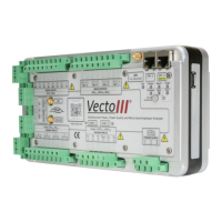
Figure 1: Front view of the Vecto III device .................................................................12
Figure 2: Packaging Opened.........................................................................................13
Figure 3: Front view of the Vecto III device .................................................................29
Figure 4: Rear view of the Vecto III device ...................................................................30
Figure 5: Right-hand view of the Vecto III device ........................................................31
Figure 6: User Interface ...............................................................................................31
Figure 7: Vecto III power supply connection................................................................32
Figure 8: Ethernet ports ...............................................................................................33
Figure 9: Vecto III 4-wire star connection ....................................................................35
Figure 10: Vecto III 3-wire delta connection ................................................................35
Figure 11: Current sensor connection..........................................................................37
Figure 12: Current transducer connection ...................................................................38
Figure 13: Relay switch connection layout ..................................................................40
Figure 14: Digital inputs connection layout .................................................................41
Figure 15: Digital input configuration for a dry contact ...............................................42
Figure 16: Digital input configuration for a wetted contact ........................................42
Figure 17: GPS antenna connector ..............................................................................43
Figure 18: Ethernet ports .............................................................................................44
Figure 19: USB port ......................................................................................................44
Figure 20: WiFi and Cellular Modem Connections .......................................................45
Figure 21: Status LEDs, On/Off button and Power Button...........................................48
Figure 22: Vecto III back as supplied by CT LAB ...........................................................52
Figure 23: Surface mount Vecto III ..............................................................................53
Figure 24: 19’’ Plate Mounting.....................................................................................53
Figure 25: Vecto III rear view as shipped by CT LAB ....................................................54
 Loading...