EasyManuals Logo

CT Lab Vecto III User Manual

CT Lab Vecto III
80 pages
To Next Page IconTo Next Page
To Previous Page IconTo Previous Page
Page #62 background imageLoading...
Page #62 background image
Vecto III User Manual
The Vecto III can be configured to:
Derive the Neutral current by the summation of the 3 line currents in star
connected (4-wire) circuits.
Derive any one of the missing line currents by the summation of the other 2
currents in Delta connected (3-wire) circuits.
4.2.4.2 Current Transducer Connections
4.2.4.2.1 Single-phase connection
The current transducer input on the Vecto III has a peak voltage input range of 2 V (1.4
V
RMS
).
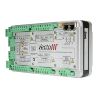
Terminal
Legend
1 V Output Current Transducer Circuits
1.
V
1+
Voltage 1
2.
V
1-
Voltage 1 Reference
3.
V
2+
None
4.
V
2-
None
5.
V
3+
None
6.
V
3-
None
7.
V
4+
None
8.
V
4-
None
Table 14: Current transducer sensor connection layout

Table of Contents

Questions and Answers:

Question and Answer IconNeed help?

Do you have a question about the CT Lab Vecto III and is the answer not in the manual?

CT Lab Vecto III Specifications

General IconGeneral
BrandCT Lab
ModelVecto III
CategoryMeasuring Instruments
LanguageEnglish