Instruments and warning/control lamps
●
In the wa
ypoints mode of the navigation
system, the traffic sign detection system is
only partly available.
●
Failure to heed the control lamps and
corresponding text messages when they
light up may result in damage to the vehi-
cle.
Time
Setting the time on the infotainment sys-
t
em
●
Pr
ess the infotainment button.
●
Press the function button SETTINGS>
Date and time to set the time
›››
page 80.
Adjusting the time in the Digital Cockpit
●
While in the Driving data menu select
the Range function (infotainment button >
View > Driving data > Range).
●
Press the button
on the multifunction
st
eering wheel until the Service menu is dis-
pla
yed on the instrument panel display
›››
page 66.
●
Select the menu Time.
●
Adjust the correct time by turning the right
thumbwheel of the multifunction steering
wheel.
Revolution counter
The rev counter indicates the number of en-
gine re
volutions per minute.
Together with the gear-change indicator,
the rev counter offers you the possibility of
using the engine of your vehicle at a suitable
speed.
The beginning of the red zone of the rev
counter indicates the maximum speed in any
gear after running-in and with the engine
hot. However, it is advisable to move the se-
lector lever to D or lift your foot off the ac-
celerator before the needle reaches the red
zone
›››
.
W
e r
ecommend that you avoid high revs and
that you follow the recommendations on the
gear-change indicator. Consult the addition-
al information in
›››
page 239, Selecting the
optimal gear.
CAUTION
●
To prevent damage to the engine, the rev
counter needle should only remain in the
red zone for a short period of time.
●
When the engine is cold, avoid high revs
and heavy acceleration and do not make
the engine work hard.
For the sake of the environment
Changing up a gear early will help you to
save fuel and minimise emissions and en-
gine noise.
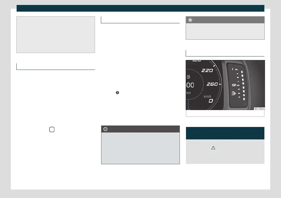
Fuel gauge
Fig. 59
Fuel gauge.
Control lamps
It lights up, and in addition, the low-
er diode lights up in red
Fuel tank almost empty. The fuel reserve level has
been reached
›››
. Refuel as soon as you have the
opportunity.
When the fuel level is very low, the lower diode flashes
red.
The display only works when the ignition is
s
wit
ched on.
»
73