User Guide DDOC0099-000-AH
DTS1 CSfC 2 - 8 Overview
© 2020 Curtiss-Wright Defense Solutions Revision 5.0
• Total of 60 impacts per unit
• Designed to meet the following environments:
• Operational Sine over Random Vibration
• MIL-STD-810E for AH-1/UH-1 Helicopter in Instrument Panel location
• Altitude: sea level to 40,000 feet
• Humidity: 0 to 95%, 20 to 55°C
• Salt Fog
• Sand and dust
• Fungus
• Explosive atmosphere
• EMI/EMC (MIL-STD-461F)
• RS101 – Magnetic Field, 30 Hz to 100 kHz
• RS103 – Electric Field, 2 MHz to 18 GHz, 200 Volt/meter
• CS101 – Power Leads, 30 Hz to 150 kHz
• CS114 – Bulk Cable Injection, 10 kHz to 200 MHz, Curve 5.
• CS115 – Bulk Cable Injection, Impulse Excitation
• CS116 – Damped Sinusoidal Transients, Cables and Power Leads 10 kHz to 100 MHz
• CE101 – Power Leads, 30 Hz to 10 kHz
• CE102 – Power Leads, 10 kHz to 10 MHz
• RE101 – Magnetic Field, 30 Hz to 100 kHz
• RE102 – Electric Field, 2 MHz to 18 GHz
• Physical
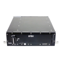
• Dimensions and mounting compliant with Military Specification MS25212
• Military/aviation rail mounting utilizing Dzus quarter-turn fasteners
• Platform mounting utilizing standard L-brackets.
• RMC module accessed via environmentally sealed front door with quarter turn locking
mechanism
• Data encryption
• Elliptical Curve Cryptography (ECC)
• AES-256, in-line battery backed-up encryption module for encryption of data-at-rest prior
to storage on RMC module
• NIST/FIPS 140-2 certifiable
• External encryption key loading
• Key may be zeroized by external hardware discrete or by software command
• RMC Module
• One module individually mounted and accessible
• Solid-state storage
• Optional capacities from 128 GB to 4 TB per RMC module.
• Low insertion/removal force: 40 oz.
• High insertion/removal cycle: > 100,000 cycles
• Hot insertion/removal
• User writeable cartridge/volume name/description (up to 32 characters) stored in cartridge
non-volatile memory accessible via out-of-band interface.
• RMC module removal request via front panel push button
• LED status indicators:
• STATUS (green): on when RMC module is installed, mounted and ready for access
• ACTIVITY (green): on when disk is accessed (not supported on some RMC module
configurations)
• FAULT (red): DTS1 system monitor has detected a fault with the RMC module


 To Next Page