●Disassembling Procedure
121
8
Disassembling Procedure
Disassembling
Procedure
Work Procedure Point
WARNING
Before disassembling work, be sure
to turn OFF all power supplies.
Procedure for Removing Switch
Box
*1
*1
When replacing the switch
box, change the setting
data referring to “Replacing
Control Board” (P.149).
*2
Disconnecting display board
Pull up the stopper of the
connector from both sides,
and disconnect the lead wire.
*3
Unless the control panel
mounting plate is removed
first, wiring of the secondary
side of the over current relay
cannot be disconnected.
*4
Once the sealing material
of the wiring port is
removed, its dust-preventive
performance is degraded.
扌
Change the removed sealing
material with a new one
before taking in lead wire
again.
1
Remove the switch box cover, top panel,
back panel, left side panel, and right side
panel in accordance with “Procedure for
Removing Outside Panel Block (P.118)”.
3.
Removing switch box
① Unscrew the four screws
fixing the switch box.
② Pull up and remove the
switch box.
①
Disconnect all the connectors and wiring
connected from outside into the switch box.
・
Primary side of power supply terminal
block (to be wired by customer)
・
Secondary side of over current relay
(*3)
・
Control board (A1P)
1)
Thermistor assembly (S9)
2)
Outlet oil thermistor (CN11)
3)
EE valve coil (S90)
4)
MO valve coil (CN7)
5)
High pressure switch (S171)*
* "C" models only
6)
Compressor protective thermostat
(S172)
7)
Signal terminal block (X2M)
・
Inverter board (A2P)
1)
Compressor (relay connector in
switch box)
2)
DC fan motor (CN15)
②
Take the lead wire off the wiring port cover.
(See page 119) (*4)
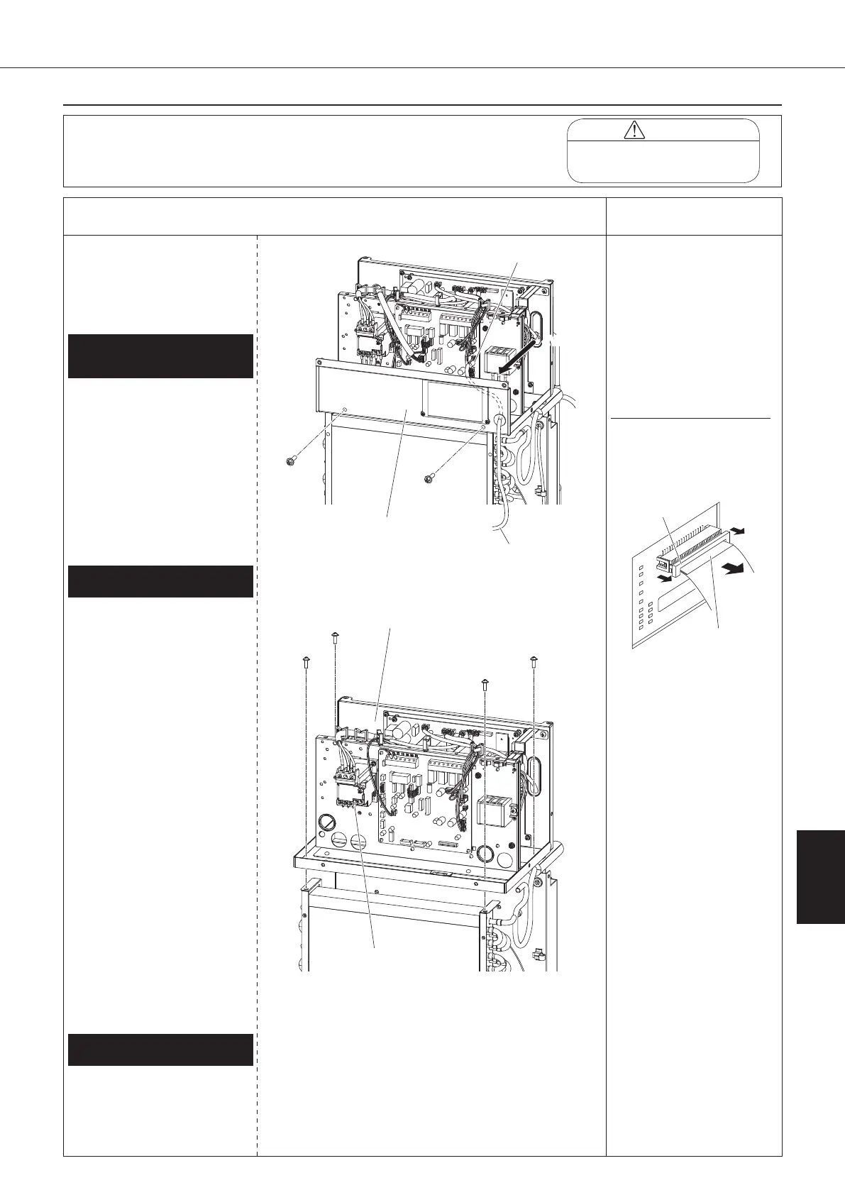
2.
Removing connected wiring to switch box
①
Disconnect the display board
connector located back of the
control panel. (*2)
②
Disconnect the room thermistor
connector (CN10) from the
control board (A1P).
③
Unscrew the two screws fixing
the control panel mounting plate
to take it.
Lead wire
1.
Removing control panel
mounting plate
Control panel
mounting plate
<View A>
Room thermistor (Th-3)
Secondary side of
over current relay
00_PB00540A_M10.indb 121 2023/08/09 12:59:11