132
8
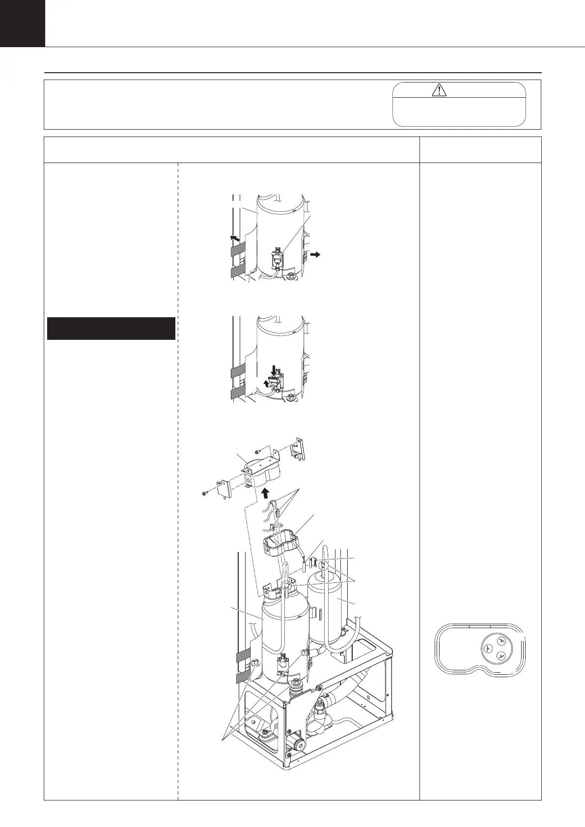
Disassembling Procedure
Work Procedure Point
WARNING
Before disassembling work, be sure
to turn OFF all power supplies.
Procedure for Removing
Compressor
*1, 2, 3
1
Remove the switch box cover,
top panel, back panel, left side
panel, and right side panel in
accordance with “Procedure for
Removing Outside Panel Block
(P.118)”.
1
Remove discharge thermistor
(Th-6) with “Procedure for
Removing Thermistors (P.130)”.
①
Recover refrigerant from the
service port.
②
Remove the protective material.
③
Remove the compressor
protection thermostat (S2T).
④
Unscrew the two screws to take
off the terminal cover.
⑤
Disconnect the lead wire
from the compressor terminal
section.
⑥
Remove the compressor
terminal cover sealing material.
⑦
Unscrew the three mounting
nuts of the compressor.
⑧
Disconnect the 2 brazing
sections to remove the
compressor (M2C).
Roll up the dew proofing tube
to expose the brazing sections
before brazing the suction pipe.
1.
Removing compressor (M2C)
*1
When replacing the
compressor (M2C), prepare
the accumulator heat insulator
(upper and lower) separately,
and attach it. Running the unit
without the accumulator heat
insulator, condensation may
occur, causing water to drip
outside the unit.
*2
Once the compressor
protection thermostat (S2T)
is removed, the radiation
sheet can no longer be used.
In that case, replace with
new one.
*3
After the compressor (M2C)
is replaced, the cumulative
compressor (M2C) running
time must be reset. Input
“
0011
”
into the parameter
n035, and reset the cumulative
compressor running time. (refer
to page 67)
After input the parameter,
turning ON the power supply
again.
*4
Compressor terminal signal
U
W
V
(Red)
(Blue)
(Yellow)
Protective material
thermostat (S2T)
(1)
(2)
(1)
While pushing the
upper part,
(2)
remove it upward.
Compressor
mounting nut
Compressor
(M2C)
Accumulator
Brazing
Discharge
thermistor (Th-6)
Terminal
cover
Compressor lead wire
Compressor terminal
cover sealing material.
00_PB00540A_M10.indb 132 2023/08/09 12:59:15