●Disassembling Procedure
139
8
Disassembling Procedure
Disassembling
Procedure
Work Procedure Point
WARNING
Before disassembling work, be sure
to turn OFF all power supplies.
1 Remove the switch box
cover in accordance with
“Procedure for Removing
Outside Panel Block
(P.133)”.
1 Remove the control
panel mounting plate
in accordance with
“Procedure for Removing
Switch Box (P.136)”.
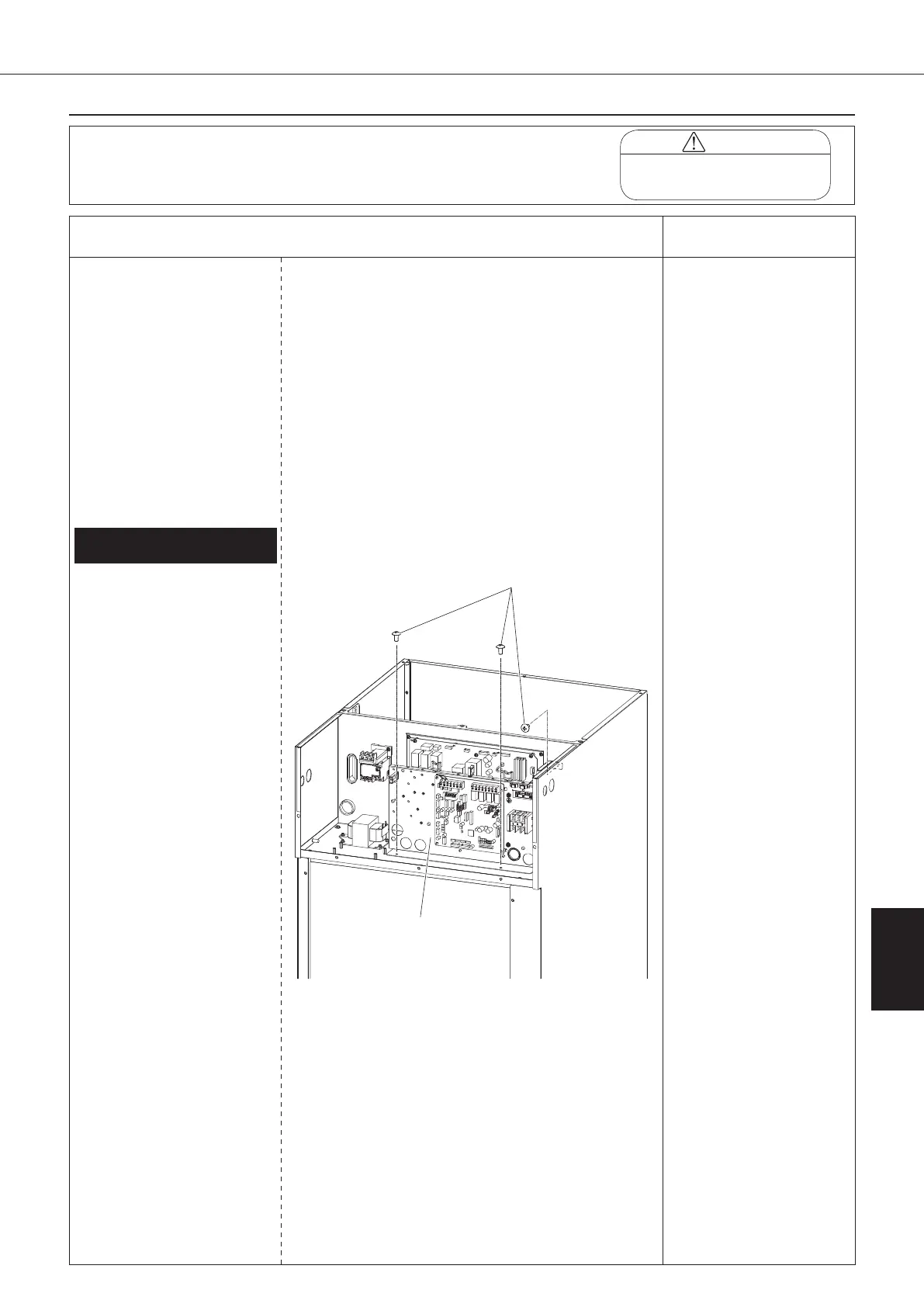
Procedure for Removing Inverter
Board (AKZ56A, 90A) (1/2)
1.
Removing inverter board (A2P)
① Unscrew the three screws
fixing the intermediate
panel.
② Disconnect all the wiring
connected to the inverter
board (A2P).
1) Compressor (relay
connector in switch
box)
2) DC fan motor (CN15)
3) Inverter board signal
wire 1 (CN6)
4) Inverter board signal
wire 2 (CN110)
5) Inverter board power
supply wire (X501)
6) Inverter board signal
wire 3 (X520)
7) Main circuit power
supply wire
(R1: HS501, S1:
HS502, T1: HS503)
8) Reactor (DCL1, DCL2)
9) Pump power supply
harness (X510)
Intermediate panel
00_PB00540A_M10.indb 139 2023/08/09 12:59:21