142
8
Disassembling Procedure
Work Procedure Point
WARNING
Before disassembling work, be sure
to turn OFF all power supplies.
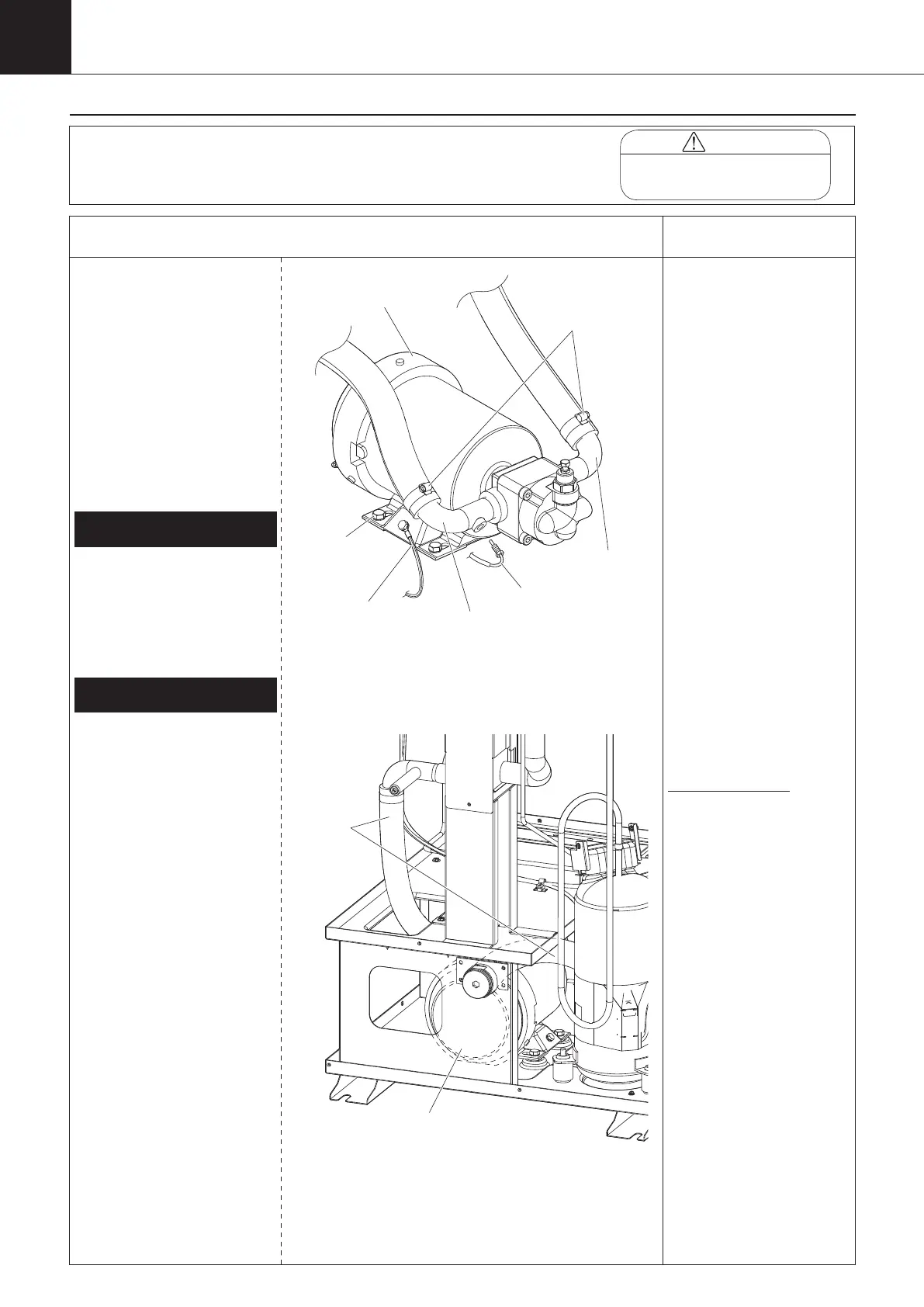
Procedure for Removing Oil
Pump
*1
*1
After the oil pump (M1P) is
replaced, the cumulative oil
pump (M1P) running time
must be reset.
Input “0012” into the
parameter n035, and reset
the cumulative pump running
time.
(refer to page 67)
*2
Removing grommet
Grommet is used to maintain
dust preventive performance
in the switch box.
扌
If any lead wire is taken out
from the grommet hole, be
sure to replace the grommet.
1
Remove the switch box cover, top
panel, back panel, left side panel,
and right side panel in accordance
with “Procedure for Removing
Outside Panel Block (P.133)”.
1
Remove the control panel mounting
plate in accordance with “Procedure
for Removing Switch Box (P.136)”
.
1
Place a receptacle to receive oil
under the evaporator.
① Loosen two hose bands
(oil outlet/inlet pipe), and
discharge oil.
② Remove the inlet oil
thermistor (Th-4).
1.
Discharging oil
① Disconnect the earth
ground wire.
② Disconnect the oil pump
lead wire connected to
the secondary side of the
overcurrent relay in the
switch box and pull it out
from the grommet (*2) of
the switch box. Remove
the band banding the oil
pump lead wires in the oil
cooling unit.
③ Unscrew the four fixing
screws from the pump.
④ Remove the two front
hose bands that are
connected to the oil pump
(M1P).
⑤ Pull the rubber hose and
remove the oil pump
(M1P).
2.
Removing oil pump (M1P)
Hose band
(two places)
Oil outlet pipe
Earth ground wire
(M1P)
Oil inlet pipe
Inlet oil thermistor
(Th-4)
Oil pump
(M1P)
00_PB00540A_M10.indb 142 2023/08/09 12:59:23