1414
MODEL NAME
Phase
and fre-
quency
Voltage
MCA
(Min.
circuit
amp.)
MOP
(Max.
overcur-
rent
protective
device)
Transmis-
sion line
selection
DZ17VSA181AA
1 Phase
60Hz
208/230V
12.7 A 15 A
18 AWG
(typical)
DZ17VSA241AA 17.4 A 20 A
DZ17VSA301AA 22.7 A 25 A
DZ17VSA361AA 22.7 A 25 A
DZ17VSA421AA 34.5 A 35 A
DZ17VSA481AA 34.5 A 35 A
DZ17VSA601AA 36.5 A 40 A
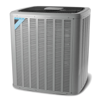
low Voltage connectIonS
The unit is designed to work as part of a fully communicat-
ing HVAC system, utilizing a Daikin approved communicat-
ing thermostat, Communicating indoor unit, and up to four
wires. Route control wires through the low voltage port and
terminate in accordance with the wiring diagram provided
inside the top plate.
<1.5 - 3.0 ton>
LOW
VOLTAGE
Tie high voltage wire with
clamp material (accessory)
HIGH
VOLTAGE
Voltage Ports
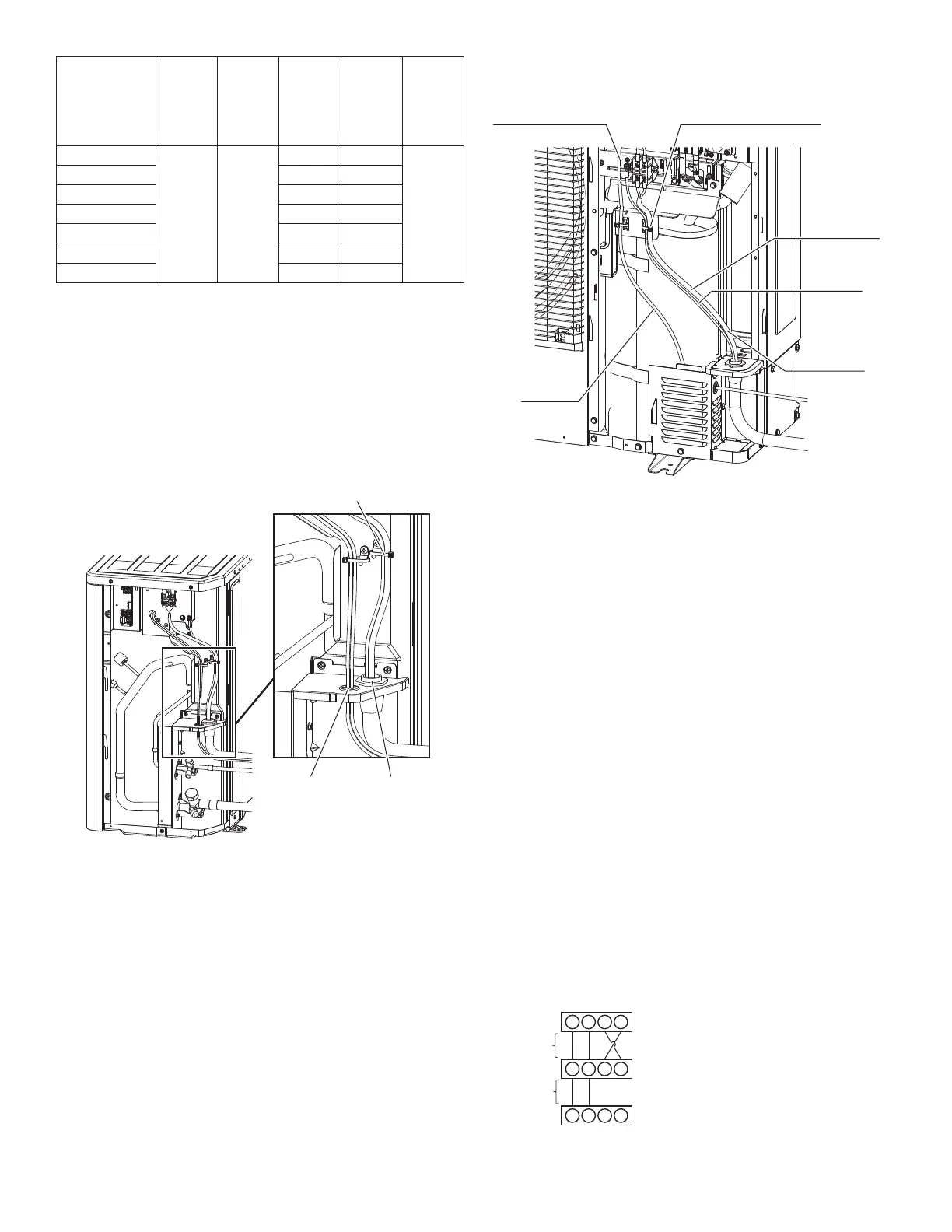
<3.5 - 5.0 ton>
Tie high voltage wire and
ground wire with clamp
material (accessory)
GROUND
WIRE
HIGH
VOLTAGE
WIRE
LOW
VOLTAGE
WIRE
SHIELDING PLATE
INSULATION
TUBE
(accessory)
Voltage Ports
NOTE: The communicating thermostat is able to search and
identify the indoor and outdoor units when power is applied to
the system. Refer to the communicating thermostat’s instal-
lation instruction manual for more information.
Connect low voltage communication wires (1, 2) to low volt-
age pigtail provided.
communIcatIon WIrIng
NOTE: A removable plug connector is provided with the
control board to make thermostat wire connections. This plug
may be removed, wire connections made to the plug, and
replaced. Do not connect multiple wires into a single terminal.
Typical 18 AWG wire may be used to wire the system compo-
nents. However, communications reliability may be improved
by using a high quality, shielded, twisted pair cable for the
data transmission lines.
tWo-WIre outdoor, four-WIre Indoor WIrIng
Low voltage wiring consists of two wires between the indoor
unit and heat pump and four wires between the indoor unit
and thermostat. The required wires are data lines 1 and 2,
“R” (24 VAC hot) and “C” (24 VAC common).
Never connect the power wiring to communication terminal.
(1, 2, R, C)
<In case of Air Handler>
(*) Allowable Maximum Length
250 .(*)
125 .(*)
Communicang Thermostat
Air Handler Blower Integrated
Control Module
Heat Pump Integrated
Control Module
1 2 C R
1 2 R C
1 2 R C
System Wiring