4949
adjuSt refrIgerant leVel
Using service equipment, add or recover refrigerant according
to the refrigerant calculation. Allow system to stabilize for 20
minutes after adjusting charge level.
meaSure SuBcoolIng to VerIfy proper charge
If want to adjust charging by checking “Subcooling”, please
follow below.
NOTE: Charging equipment must use dedicated PVE oil
gauges and hoses.
1. Purge gauge lines.
2. Connect service gauge manifold to liquid base valve
service ports.
3. Convert the liquid pressure to temperature using a
temperature/pressure chart.
4. Temporarily install a thermometer on the liquid line at
the liquid line service valve.
Ensure the thermometer makes adequate contact and
is insulated for best possible readings.
5. Subtract the liquid line temperature from the converted
liquid pressure to determine subcooling.
6. Before starting the subcooling adjustment, make sure
the outdoor ambient temperature is in a below range
and the unit is operating at 100% capacity.
If the unit is operating at 100% capacity which is ready
for charge by subcooling, seven segments will light up
as “cha”.
But, if the unit is not operating at 100% capacity which
is not ready for charging, seven segments will ush
as “cha”.
7. If the system subcooling is not within the range
as shown in the following table, adjust subcooling
according to the following procedure.
a. If subcooling is low, add charge to adjust the
subcooling as specied in the following table.
b. If subcooling is high, remove charge to lower the
subcooling to below charging table value.
SUBCOOLING = (SAT. LIQUID TEMP.) - (LIQUID LINE
TEMP.)
Charging Table
OD Ambient
Temp (degF)
< 65 °F 65°F to 105°F > 105 °F
Subcooling
(degF)
Weigh in
Charge
1.5 T - 10 ±1°F
2.0 T - 12 ±1°F
2.5 T - 14 ±1°F
3.0 T - 14 ±1°F
3.5 T - 10 ±1°F
4.0 T - 8 ±1°F
5.0 T - 9 ±1°F
Weigh in
Charge
Note: Subcooling information is valid only while the unit is operating at
100% capacity or 100% of compressor speed in CHARGE MODE.
Compressor speed is displayed under STATUS menu in the thermostat.
NOTE: Not more than 3/8 lb. (6 oz.) of refrigerant be added
to the system at a time to achieve the target subcooling. It is
recommended adding 1 oz. refrigerant each time, then wait
10 minutes to stabilize the system.
check the Schrader portS for leakS and tIghten ValVe coreS, If
neceSSary. InStall capS fInger-tIght.
NOTICE
do not adjuSt the charge BaSed on SuctIon preSSure.
NOTICE
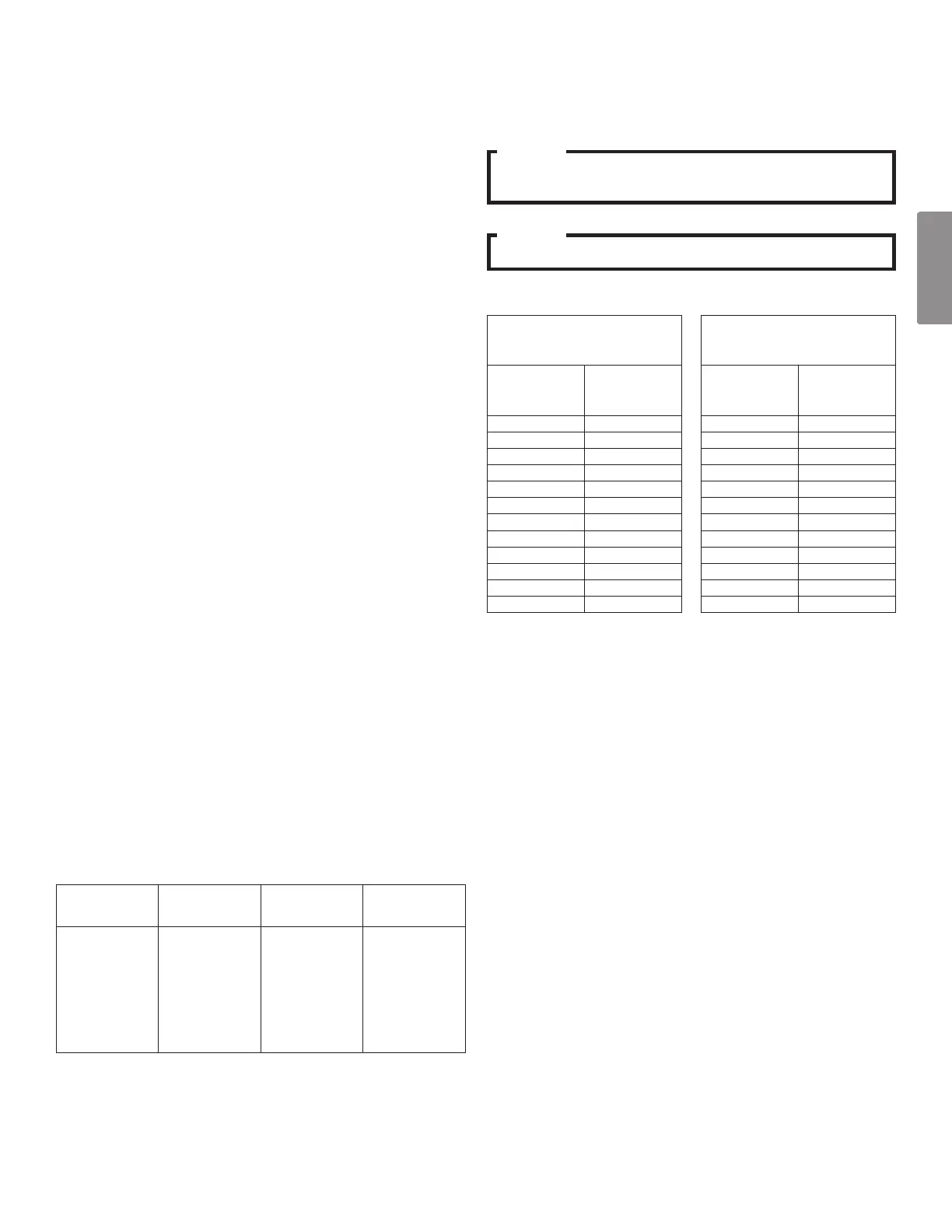
SATURATED LIQUID
PRESSURE TEMPERATURE
CHART
SATURATED LIQUID
PRESSURE TEMPERATURE
CHART
LIQUID
PRESSURE
PSIG
R-410A
°F
LIQUID
PRESSURE
PSIG
R-410A
°F
200 70 325 101
210 73 355 108
220 76 375 112
225 78 405 118
235 80 415 119
245 83 425 121
255 85 435 123
265 88 445 125
275 90 475 130
285 92 500 134
295 95 525 138
305 97 550 142
heat pump wIth outdoor temperature lockoutS
It is recommended to set the outdoor temperature lockouts
during the initial thermostat set up. Compressor lockout
temperature will enable the compressor to be turned off and
switch heating source from refrigeration to auxiliary/secondary
heating under low outdoor ambient conditions.
In case of 30 ft. or longer line set application, refrigerant may
be accumulated inside line set pipe. Select 15°F or higher
compressor (heat pump) lockout temperature to set heat
pump lockout.
Backup heat lockout temperature will enable auxiliary/sec-
ondary heating to be turned on when outdoor temperature
is much higher than indoor temperature, compressor might
stop operating under this circumstance.
In order to access temperature, the compressor lockout and
the backup heat lockout, press MENU and scroll down to
press INSTALLER OPTIONS. Enter the date code (password)
when prompted. Choose VIEW / EDIT CURRENT SETUP
and COMPRESSOR LOCKOUT / BALANCE POINT will be
under HEAT / COOL CONTROL OPTIONS. For more infor-
mation please refer to Communicating Thermostat SYSTEM
INSTALLATION GUIDE.