Group 20: Limits
This group denes minimum and maximum limits to follow in driving the motor –speed, frequency, current, torque, etc.
Table 12: Group 20 — Limits
Code Name Range Resolution Default User S
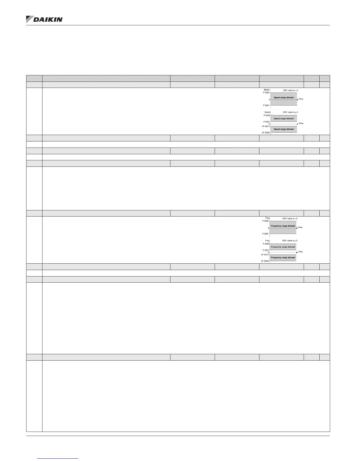
2001 MINIMUM SPEED -30000…30000 rpm 1 rpm 0 rpm
Denes the minimum speed (rpm) allowed.
• A positive (or zero) minimum speed value denes two ranges, one positive and one negative.
• A negative minimum speed value denes one speed range.
• See the gure.
2002 MAXIMUM SPEED 0…30000 rpm 1 rpm 1800 rpm (US)
Denes the maximum speed (rpm) allowed.
2003 MAX CURRENT 0… 1.3 · I2
n
0.1 A 1.3 · I2
n
Denes the maximum output current (A) supplied by the drive to the motor.
2006 UNDERVOLT CTRL 0…2 1 1 [ENABLE(TIME)]
Sets the DC undervoltage controller on or off. When on:
• If the DC bus voltage drops due to loss of input power, the undervoltage controller decreases the motor speed in order to keep the DC bus voltage
above the lower limit.
• When the motor speed decreases, the inertia of the load causes regeneration back into the drive, keeping the DC bus charged and preventing an
undervoltage trip.
• The DC undervoltage controller increases power loss ride-through on systems with a high inertia, such as a centrifuge or a fan.
0 = DISABLE – Disables controller.
1 = ENABLE(TIME) – Enables controller with 500 ms time limit for operation.
2 = ENABLE – Enables controller without maximum time limit for operation.
2007 MINIMUM FREQ -500.0…500.0 Hz 0.1 Hz 0.0 Hz
Denes the minimum limit for the drive output frequency.
• A positive or zero minimum frequency value denes two ranges, one positive and one negative.
• A negative minimum frequency value denes one speed range. See the gure.
Note: Keep MINIMUM FREQ ≤ MAXIMUM FREQ.
2008 MAXIMUM FREQ 0.0…500.0 Hz 0.1 Hz 60.0 Hz (US)
Denes the maximum limit for the drive output frequency.
2013 MIN TORQUE SEL -6…7 1 0 (MIN TORQUE 1)
Denes control of the selection between two minimum torque limits (2015 MIN TORQUE 1 and 2016 MIN TORQUE 2).
0 = MIN TORQUE 1 – Selects 2015 MIN TORQUE 1 as the minimum limit used.
1 = DI1 – Denes digital input DI1 as the control for selecting the minimum limit used.
• Activating the digital input selects MIN TORQUE 2 value.
• De-activating the digital input selects MIN TORQUE 1 value.
2…6 = DI2…DI6 – Denes digital input DI2…DI6 as the control for selecting the minimum limit used.
• See DI1 above.
7 = COMM – Denes bit 15 of the Command Word 1 as the control for selecting the minimum limit used.
• The Command Word is supplied through eldbus communication.
• The Command Word is parameter 0301.
-1 = DI1(INV) – Denes an inverted digital input DI1 as the control for selecting the minimum limit used.
• Activating the digital input selects MIN TORQUE 1 value.
• De-activating the digital input selects MIN TORQUE 2 value.
-2…-6 = DI2(INV)…DI6(INV) – Denes an inverted digital input DI2…DI6 as the control for selecting the minimum limit used.
• See DI1(INV) above.
2014 MAX TORQUE SEL -6…7 1 0 (MAX TORQUE 1)
Denes control of the selection between two maximum torque limits (2017 MAX TORQUE 1 and 2018 MAX TORQUE 2).
0 = MAX TORQUE 1 – Selects 2017 MAX TORQUE 1 as the maximum limit used.
1 = DI1 – Denes digital input DI1 as the control for selecting the maximum limit used.
• Activating the digital input selects MAX TORQUE 2 value.
• De-activating the digital input selects MAX TORQUE 1 value.
2…6 = DI2…DI6 – Denes digital input DI2…DI6 as the control for selecting the maximum limit used.
• See DI1 above.
7 = COMM – Denes bit 15 of the Command Word 1 as the control for selecting the maximum limit used.
• The Command Word is supplied through eldbus communication.
• The Command Word is parameter 0301.
-1 = DI1(INV) – Denes an inverted digital input di1 as the control for selecting the maximum limit used.
• Activating the digital input selects MAX TORQUE 1 value.
• De-activating the digital input selects MAX TORQUE 2 value.
-2…-6 = DI2(INV)…DI6(INV) – Denes an inverted digital input DI2…DI6 as the control for selecting the maximum limit used.
• See DI1(INV) above
OM 1191 • MD5 VFD 28 www.DaikinApplied.com
ParaMeTers