Mechanical and Electrical Installation–EFB
WARNING
Connections should be made only while the drive is
disconnected from the power source.
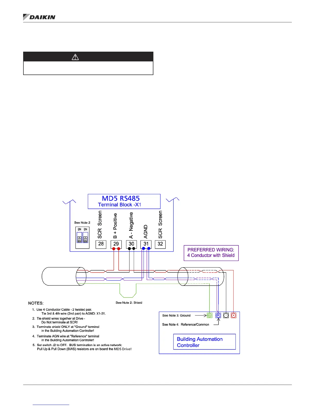
• Use Belden 9842 or equivalent. Belden 9842 is a dual
twisted, shielded pair cable with a wave impedance of
120 Ω.
• Use one of these twisted shielded pairs for the RS485
link. Use this pair to connect all A (-) terminals together
and all B (+) terminals together.
• Use one of the wires in the other pair for the reference/
common (terminal 31), leaving one wire unused.
• Do not directly ground the RS485 network at any
point. Ground all devices on the network using their
corresponding earthing terminals.
• As always, the grounding wires should not form any
closed loops, and all the devices should be earthed to a
common ground.
• Connect the RS485 link in a daisy-chained bus, without
dropout lines.
• To reduce noise on the network, terminate the RS485
network using 120 Ω resistors at both ends of the
network. Use the DIP switch to connect or disconnect the
termination resistors. See following wiring diagram. The
MD5 termination resistor (J-2) are active terminators. This
active circuit includes bins (“Pull-up” and “Pull-down”)
resistors.
• Connect the shield at each end of the cable to a drive.
On one end, connect the shield to terminal 28, and on
the other end connect to terminal 32. Do not connect
the incoming and outgoing cable shields to the same
terminals, as that would make the shielding continuous.
• For conguration information see the following:
— Communication Setup – EFB on page 48.
— Activate Drive Control Functions – EFB on page
50
..
Figure 7: Preferred Wiring Diagram
OM 1191 • MD5 VFD 46 www.DaikinApplied.com
eMbedded fieldbUs