Activate Drive Control Functions – EFB
Controlling the Drive
Fieldbus control of various drive functions requires
conguration to:
• Tell the drive to accept eldbus control of the function.
• Dene as a eldbus input, any drive data required for
control.
• Dene as a eldbus output, any control data required by
the drive.
The following sections describe, at a general level, the
conguration required for each control function. For the
protocol-specic details, see the document supplied with the
FBA module.
Start/Stop Direction Control
Using the eldbus for start/stop/direction control of the drive
requires:
• Drive parameter values set as dened below.
• Fieldbus controller supplied command(s) in the
appropriate location. (The location is dened by the
Protocol Reference, which is protocol dependent.)
NOTE: EXT1 = REF1 typically used for follower; EXT2 =
REF2 typically used for PID setpoint.
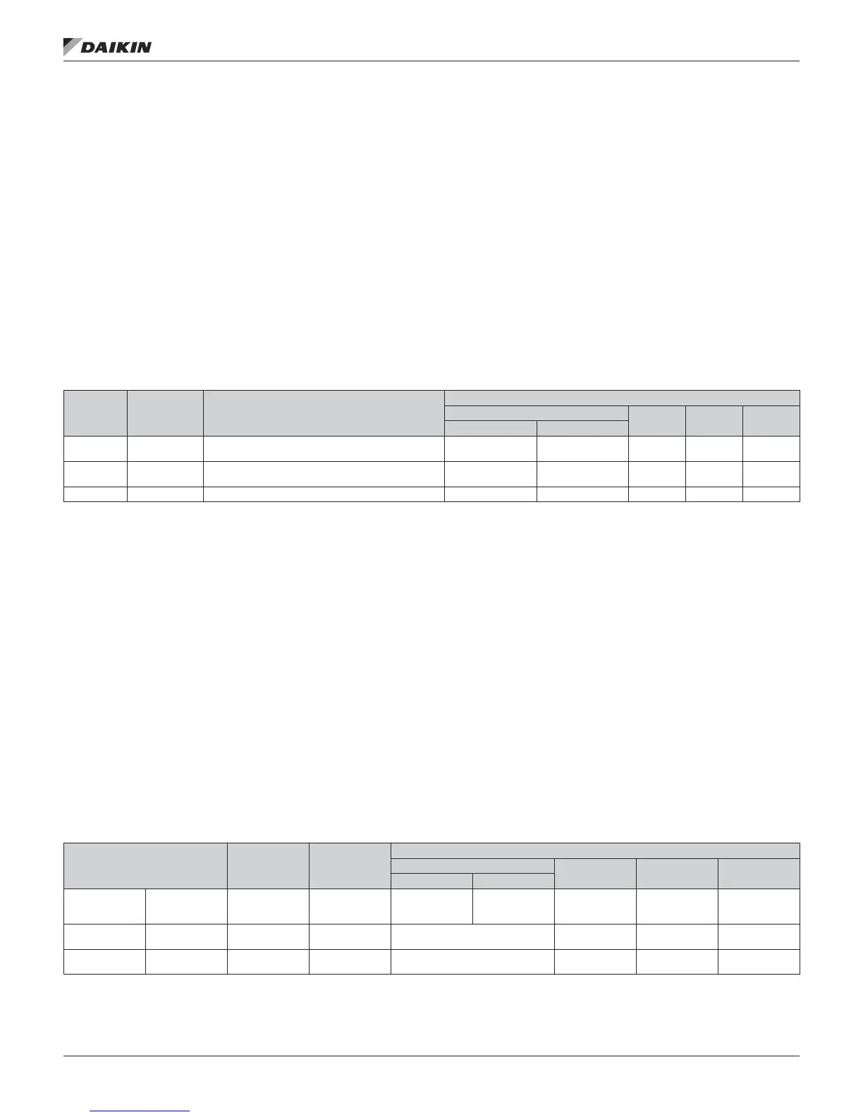
Table 26: Start/Stop Direction Parameters
Drive
Parameter
Value Description
Protocol Reference
Modbus1
N2 FLN BACnet
Daikin DRV DCU PROFILE
1001
EXT1
COMMANDS
10 (COMM) Start/Stop by eldbus with Ext1 selected. 40001 bits 0…3 40031 bits 0, 1 BO 24 BV10
1002
EXT2
COMMANDS
10 (COMM) Start/Stop by eldbus with Ext2 selected. 40001 bits 0…3 40031 bits 0, 1 BO1 24 BV10
1003 DIRECTION 3 (REQUEST) Direction by eldbus. 4002/4003
2
40031 bit 3 BO2 22 BV11
1. For Modbus, the protocol reference can depend on the prole used, hence two columns in these tables. One column refers to the Daikin Drives prole, selected when parameter 5305 = 0
(Daikin DRV LIM) or 5305 = 2 (Daikin DRV FULL). The other column refers to the DCU prole selected when parameter 5305 = 1 (DCU PROFILE). See Daikin control proles technical data
section.
2. The reference provides direction control – a negative reference provides reverse rotation.
Input Reference Select
Using the eldbus to provide input references to the drive
requires:
• Drive parameter values set as dened below.
• Fieldbus controller supplied reference word(s) in the
appropriate location. (The location is dened by the
Protocol Reference, which is protocol dependent.)
Reference Scaling
Where required, REFERENCES can be scaled. See the
following, as appropriate:
• Modbus Register 40002 in the Modbus protocol technical
data section.
• Reference scaling in the Daikin control proles technical
data section.
• N2 analog output objects in the N2 protocol technical
data section.
• The slope of points 60 and 61 in the FLN protocol
technical data section.
Table 27: Input Reference Parameters
Drive Parameter Value Setting
Protocol Reference
Modbus
N2 FLN BACnet
Daikin DRV DCU PROFILE
1102 EXT1/EXT2 SEL 8 (COMM)
Reference set
selection by
eldbus.
40001 bit 11 40031 bit 5 BO5 26 BV13
1103 REF1 SEL 8 (COMM)
Input reference
1 by eldbus.
40002 AO1 60 AV16
1106 REF2 SEL 8 (COMM)
Input reference
2 by eldbus.
40003 AO2 61 AV17
OM 1191 • MD5 VFD 50 www.DaikinApplied.com
eMbedded fieldbUs