fieldbUs adaPTer
Overview
The MD5 can be set up to accept control from an external
system using standard serial communication protocols. When
using serial communication, the MD5 can either:
• Receive all of its control information from the eldbus, or
• Be controlled from some combination of eldbus control
and other available control locations, such as digital or
analog inputs, and the control panel.
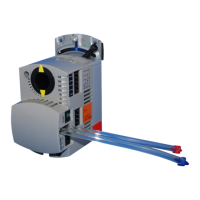
Figure 10: Available Control Locations
Two basic serial communications congurations are available:
• Embedded eldbus (EFB) – See Embedded Fieldbus on
page 45.
• Fieldbus adapter (FBA) – With one of the optional
FBA modules in the drive’s expansion slot 2, the drive
can communicate to a control system using one of the
following protocols:
— Probus-DP
®
— LonWorks
®
— CANopen
®
— DeviceNet
®
— ControlNet
®
— Ethernet
®
The MD5 detects automatically which communication
protocol is used by the plug-in eldbus adapter. The default
settings for each protocol assume that the prole used is the
protocol’s industry-standard drive prole (e.g. PROFIdrive
for PROFIBUS, AC/DC Drive for DeviceNet). All of the FBA
protocols can also be congured for the Daikin Drives prole.
Conguration details depend on the protocol and prole used.
These details are provided in a user’s manual supplied with the
FBA module.
Details for the Daikin Drives prole (which apply for all
protocols) are provided in Daikin drives prole technical data
on page 89.
Control interface
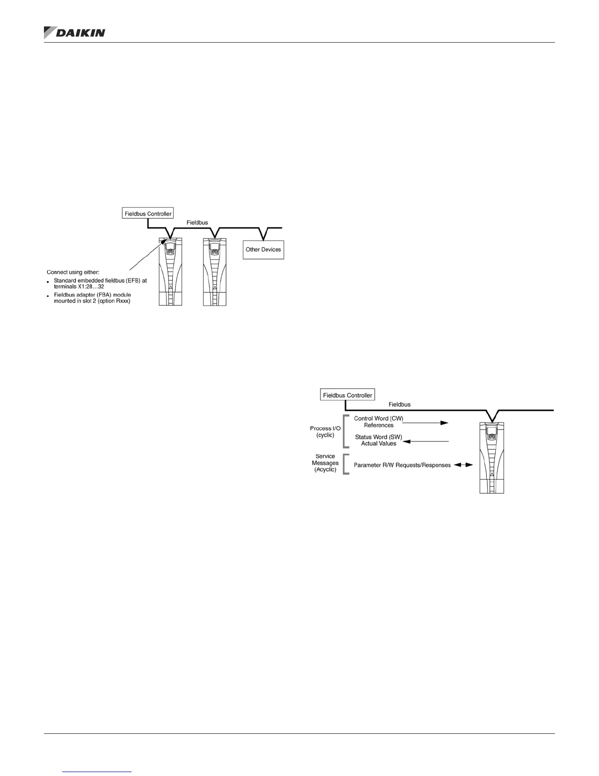
In general, the basic control interface between the eldbus
system and the drive consists of:
• Output Words:
— CONTROL WORD
— REFERENCE (speed or frequency)
— Others: The drive supports a maximum of 15 output
words. Protocols limits may further restrict the total.
• Input Words:
— STATUS WORD
— Actual Value (speed or frequency)
— Others: The drive supports a maximum of 15 input
words. Protocols limits may further restrict the total.
NOTE: The words “output” and “input” are used as seen from
the eldbus controller point of view. For example an
output describes data ow from the eldbus controller
to the drive and appears as an input from the drive
point of view.
The meanings of the controller interface words are not
restricted by the MD5. However, the prole used may set
particular meanings.
Figure 11: Controller Interface Words
fieldbUs adaPTer
www.DaikinApplied.com 67 OM 1191 • MD5 VFD