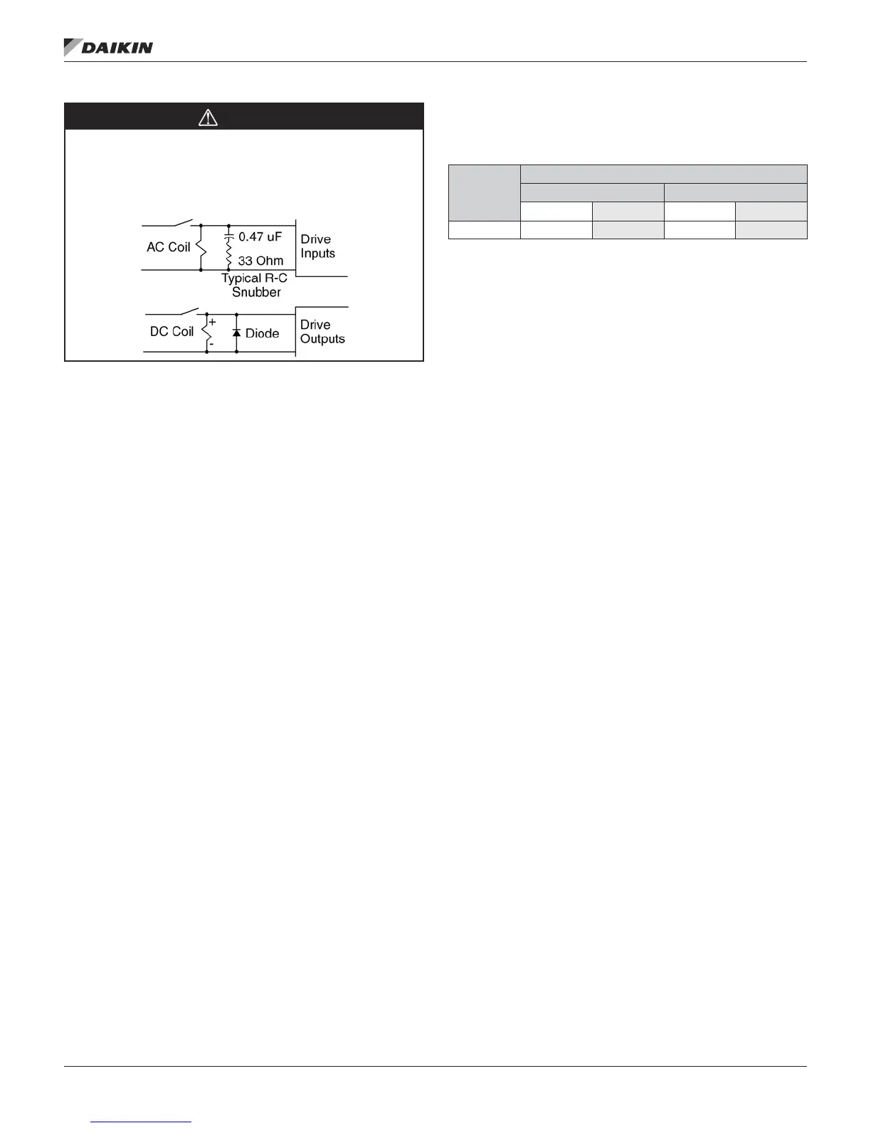
WARNING
Relay coils generate noise spikes in response to steps in
applied power. To avoid drive damage from such spikes,
all AC relay coils mounted across drive inputs require R-C
snubbers, and all DC relay coils mounted across drive outputs
require diodes – see gure.
Analog Cables
Recommendations for analog signal runs:
• Use double shielded, twisted pair cable.
• Use one individually shielded pair for each signal.
• Do not use a common return for different analog signals.
Digital Cables
Recommendation for digital signal runs: A double shielded
cable is the best alternative, but single-shielded, twisted, multi-
pair cable is also usable.
Control Panel Cable
If the control panel is connected to the drive with a cable, use
only Category 5 Patch ethernet cable.
Drive’s Control Connection Terminals
The following table provides specications for the drive’s
control terminals
Frame Size
Control
Maximum Wire Size Torque
mm2 AWG Nm lb-ft
All 1.5 16 0.4 0.3
Control Terminal Descriptions
The following full-page diagram provides a general description
of the control terminals on the drive. For specic application
details, see the Application Macros on page 9.
NOTE: Terminals 3, 6, and 9 are at the same potential.
For safety reasons the fault relay signals a “fault”
when the MD5 is powered down.
TeChniCal daTa
www.DaikinApplied.com 85 OM 1191 • MD5 VFD