Table 62: Drive Control Terminal Descriptions
X1 Drive Control Terminal Description
Analog I/O
1 SCR Terminal for signal cable screen. (Connected internally to chassis ground.)
2 AI1
Analog input channel 1, programmable. Default
2
= external reference. Resolution 0.1%, accuracy ±1%.
J1:AI1 OFF: 0(2)…10 V (Ri = 312 kΩ) or, for OFF for ON
J1:AI1 ON: 0(4)…20 mA (Ri = 100 Ω)
3 AGND Analog input circuit common (connected internally to chassis gnd. through 1 MΩ).
4 +10 V Potentiometer reference source: 10 V ±2%, max. 10 mA (1kΩ < R < 10kΩ).
5 AI2
Analog input channel 2, programmable. Default
2
= PID feedback. Resolution 0.1%, accuracy ±1%.
J1:AI2 OFF: 0(2)…10 V (Ri = 312 kΩ) or, for OFF for ON
J1:AI2 ON: 0(4)…20 mA (Ri = 100 Ω)
6 AGND Analog input circuit common (connected internally to chassis gnd. through 1 MΩ).
7 AO1
Analog output, programmable. Default
2
= frequency. 0…20 mA (load < 500 Ω).
8 AO2
Analog output, programmable. Default
2
= current. 0…20 mA (load < 500 Ω).
9 AGND Analog output circuit common (connected internally to chassis gnd. through 1 MΩ).
Digital Inputs
1
10 +24V. Auxiliary voltage output 24 VDC / 250 mA (reference to GND), short circuit protected
11 GND Auxiliary voltage output common (connected internally as oating).
12 DCOM
Digital input common. To activate a digital input, there must be ≥+10 V (or ≤-10 V) between that input and DCOM. The 24 V may be
provided by the MD5 (X1-10) or by an external 12…24 V source of either polarity.
13 DI1 Digital input 1, programmable. Default
2
= start/stop.
14 DI2 Digital input 2, programmable. Default
2
= not congured.
15 DI3
Digital input 3, programmable. Default
2
= constant (preset) speed.
16 DI4 Digital input 4, programmable. Default
2
= safety interlock.
17 DI5 Digital input 5, programmable. Default
2
= not congured.
18 DI6
Digital input 6, programmable. Default
2
= not congured.
Relay Outputs
19 RO1C Relay output 1, programmable. Default
2
= Ready
Maximum: 250 VAC / 30 VDC, 2 A
Minimum: 500 mW (12 V, 10 mA)
20 RO1A
21 RO1B
22 RO2C
Relay output 2, programmable. Default2 = Running
Maximum: 250 VAC / 30 VDC, 2 A
Minimum: 500 mW (12 V, 10 mA)
23 RO2A
24 RO2B
25 RO3C
Relay output 3, programmable. Default2 = Fault (-1)
Maximum: 250 VAC / 30 VDC, 2 A
Minimum: 500 mW (12 V, 10 mA)
26 RO3A
27 RO3B
1 Digital input impedance 1.5 kΩ. Maximum voltage for digital inputs is 30 V.
2 Default values depend on the macro used. Values specied are for the HVAC default macro. See Application Macros on page 9
.
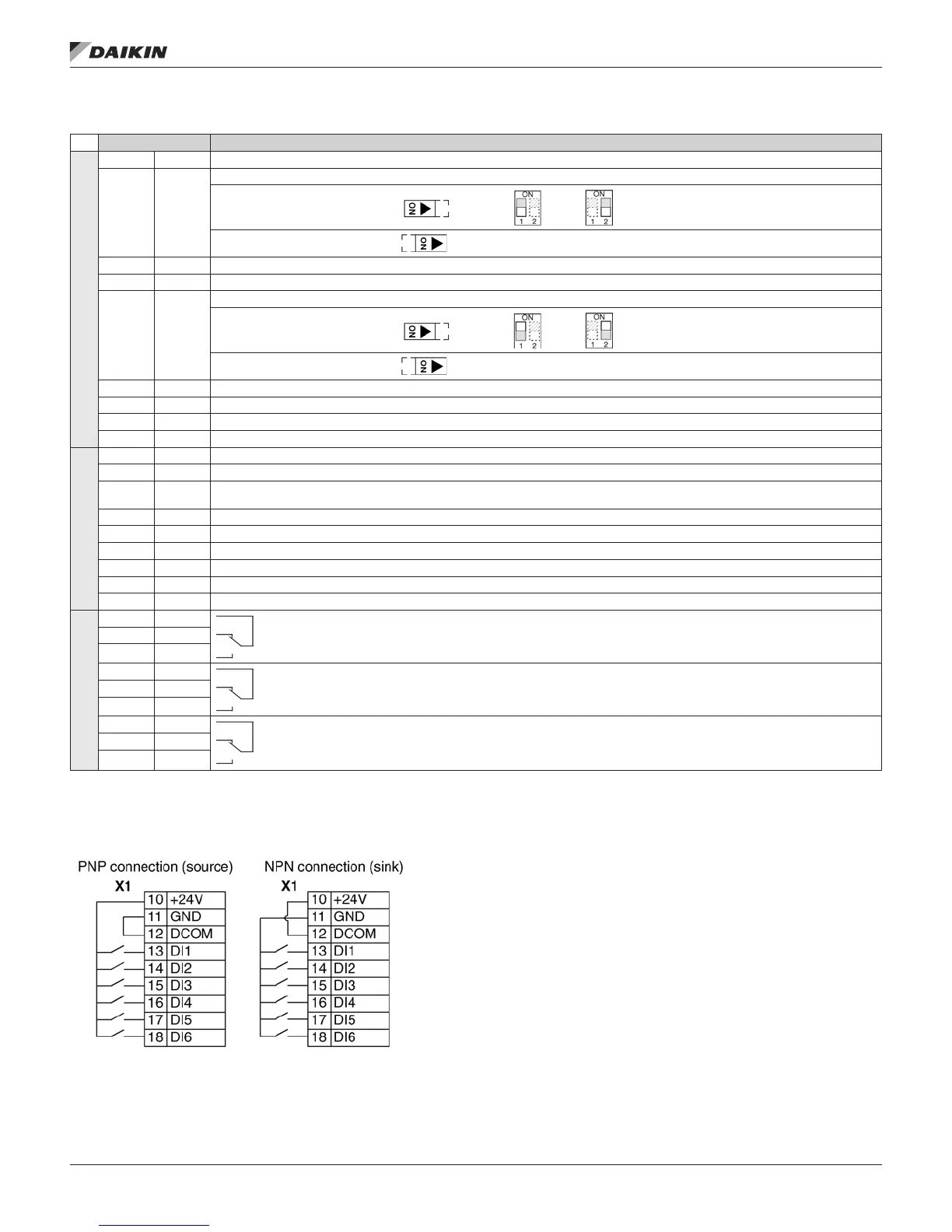
You can wire the digital input terminals in either a PNP or NPN
conguration.
Serial Communications
Terminals 28…32 provide RS485 serial communication
connections used to control or monitor the drive from a eldbus
controller. See Embedded Fieldbus on page 45 for details.
OM 1191 • MD5 VFD 86 www.DaikinApplied.com
TeChniCal daTa