Refrigerant System Diagram Si33-105
42 Function R407C PLUS Series Heat Recovery System
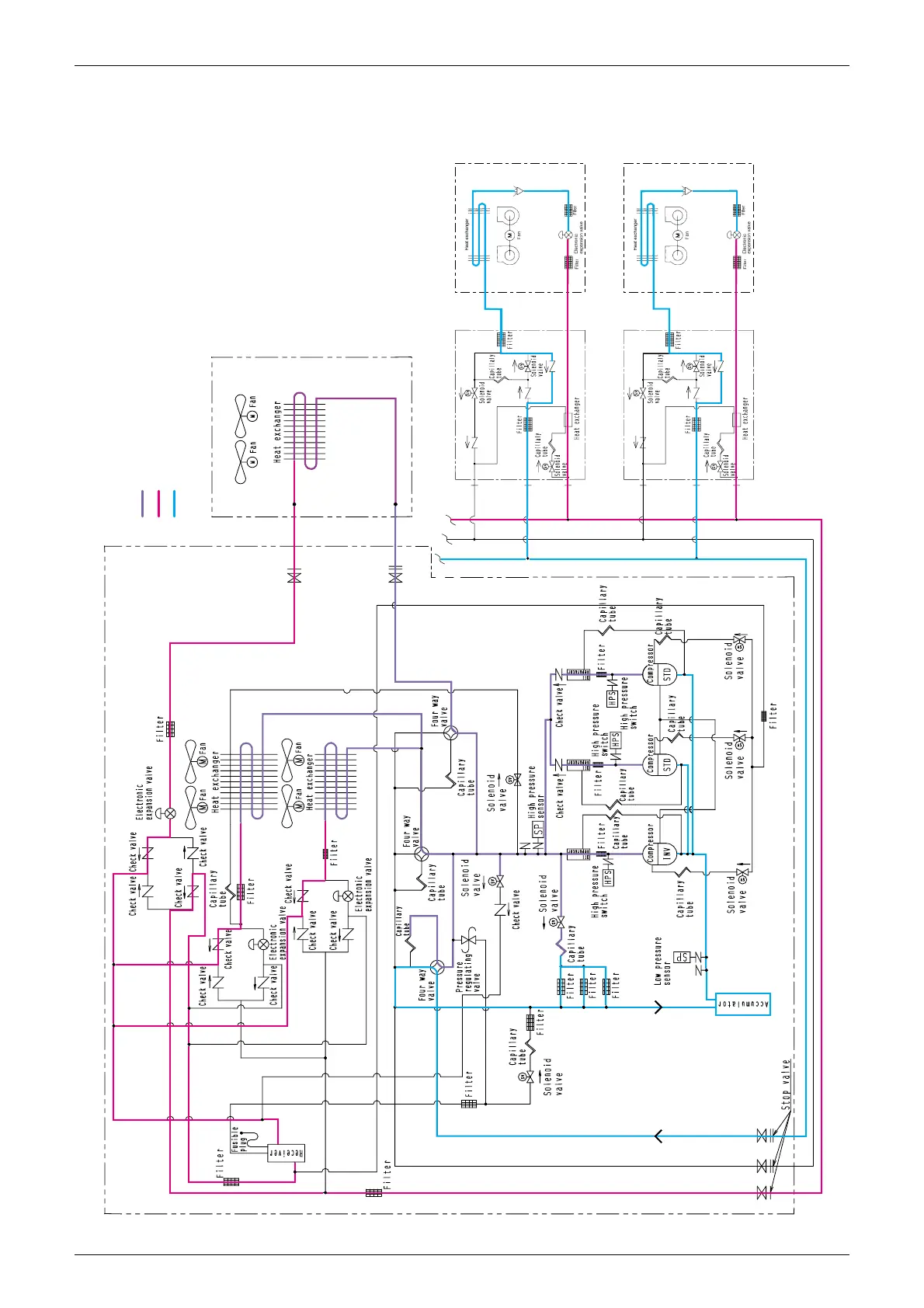
1.3.4 Oil Return Operation-Discharge (at Heating and Simultaneous
Cooling / Heating Operation or Defrost Operation)
Cooling operation indoor unit
Heating operation indoor unit
BS unit
BS unit
Main unit
Sub unit
Hex.3
(Y3E)
20E3
Hex. 1
20E1(Y1E)
Hex. 2
20S1(Y1R)
20S2
(R1R)
Y5S
(3D031938-5)
20E2
(Y2E)
20S3
(Y3R)
Note) This diagram shows a suction operation, and refer to the outline
control for the details of oil return and defrosting operation.
High pressure & high temperature gas refrigerant
High pressure & high temperature liquid refrigerant
Low pressure & low temperature liquid & gas refrigerant