A·X·U·M User Manual Version 2.5 - 2011-01-28
AXUM from D&R - Phone: +31 294 418014 - E-Mail: info@d-r.nl - 68 -
10 Available I/O rack cards
Depending on your audio-connections, you can select the I/O cards.
The next paragraphs will give you a detailed overview on the currently available cards.
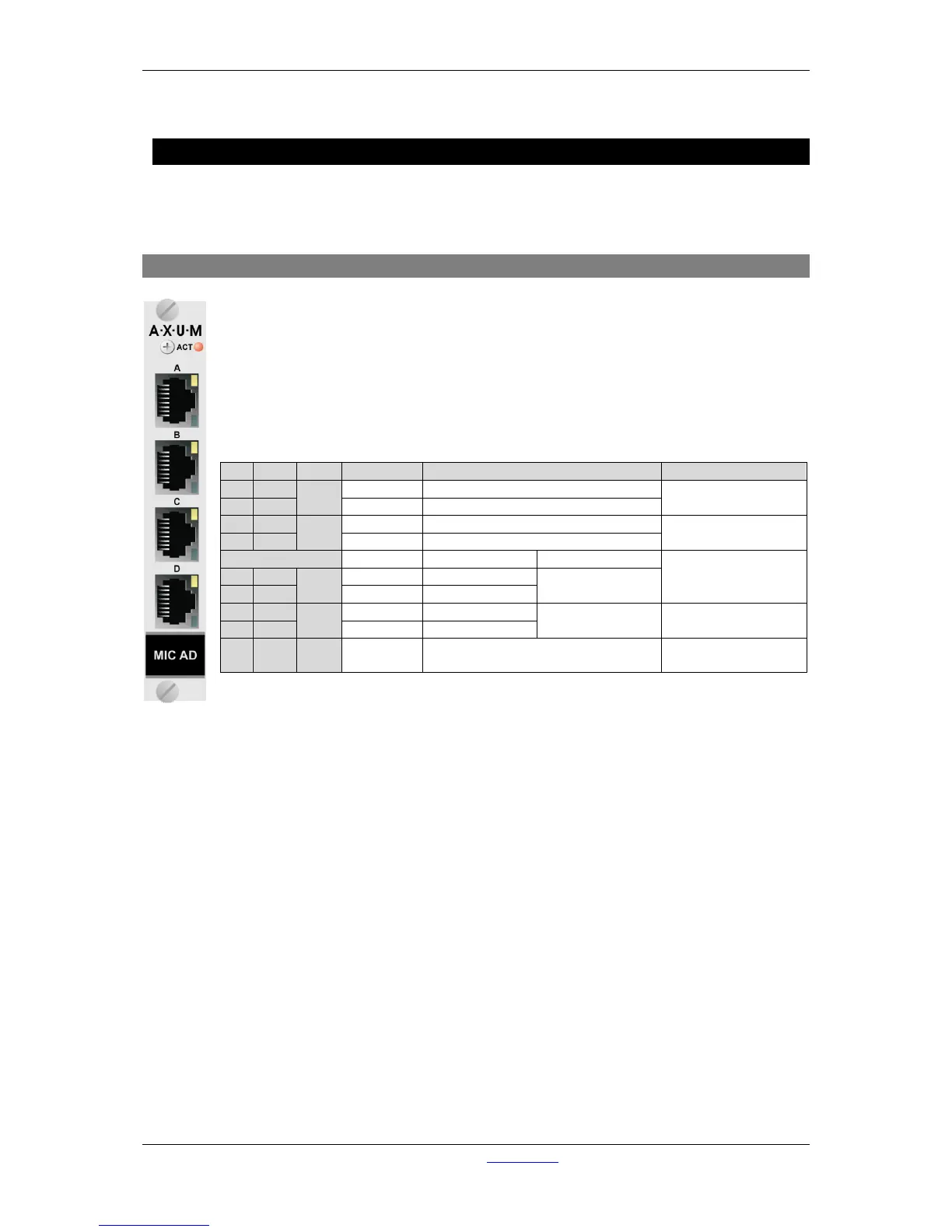
10.1 MIC input card
There are four balanced MIC inputs available on each card.
Each RJ45 connector represents a MIC input and two GPIO’s which can be connected to
the 19” patch panels with a shielded twisted pair (STP) cable.
On each MIC input you can individual activate the +48V phantom power and PAD.
For each GPIO you can choose, by way of a hardware jumper on the board, between TTL
Input/output or Photo-MOS relay output see chapter 11.3.1 GPIO TTL/Relay selection. For
software configuration see chapter 9.3 GPIO.
Table 10-1: MIC RJ45 connection