A·X·U·M User Manual Version 2.5 - 2011-01-28
AXUM from D&R - Phone: +31 294 418014 - E-Mail: info@d-r.nl - 79 -
11.2 Wiring
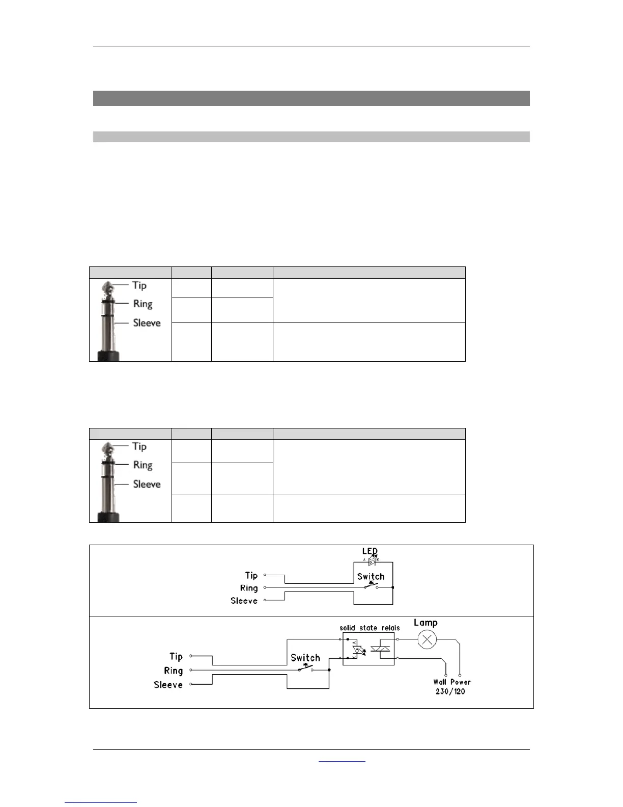
11.2.1 GPIO/Remote
The remote jack connects to all kinds of remote in-/outputs. Such as remote start/stop, external red
lights or cough. The function of the remote jack depends on the I/O card and function setup for this
GPIO. The software determines its function and where it is connected to.
! NEVER CONNECT HIGH POWER VOLTAGE (WALL POWER) TO THE REMOTE-JACK !
If the GPIO jumper setting on the Axum-Rack-Board is set for GPO the remote becomes only a
Remote-Output by a build in Solid State Relay. The relay is situated between Tip and Ring of the
remote jack.
Normally the GPIO jumper setting on the Axum-Rack-boards are set for GPO.
Ring GP-NO
Sleeve Shield Ground
Table : GPO Patch Panel wiring
If the GPIO jumper setting on the Axum-rack-Board is set for GPIO the remote becomes a Remote-
Output GPO (+5V TTL) on the Tip of the remote jack and a Remote-Input GPI (+5V TTL internal pull-
up) on the Ring. The Sleeve is Shield and the ground for the TTL signal.