A·X·U·M User Manual Version 2.5 - 2011-01-28
AXUM from D&R - Phone: +31 294 418014 - E-Mail: info@d-r.nl - 70 -
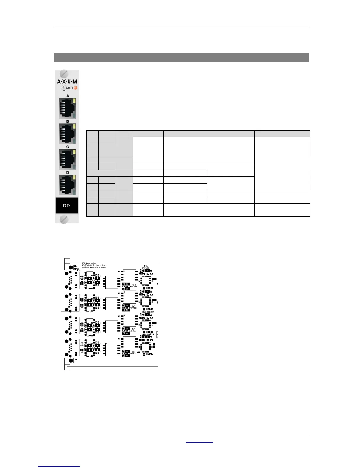
10.3 Digital in/output card (optional SRC)
There are four balanced digital inputs and outputs available on each card.
Each RJ45 connector represents a stereo line input and two GPIO’s which can be
connected to the 19” patch panels with a shielded twisted pair (STP) cable.
There is also a card available with built in sample rate converters (SRC).
For each GPIO you can choose, by way of a hardware jumper on de board, between TTL
Input/output or Photo-MOS relay output see chapter 11.3.1 GPIO TTL/Relay selection. For
software configuration see chapter 9.3 GPIO.
Table 10-3: Digital input/output RJ45 connection
With jumper on the I/O card it is possible to select the impedance for S/P-DIF (75Ω) or AES-3 (110 Ω)
This figures shows the jumper location on the I/O card
Figure 46: Digital S/P-DIF or AES3 selection