EasyManua.ls Logo

D&R AXUM - 10.2 Line Input Card Specifications

D&R AXUM
121 pages
Print Icon
To Next Page IconTo Next Page
To Previous Page IconTo Previous Page
Loading...
A·X·U·M User Manual Version 2.5 - 2011-01-28
AXUM from D&R - Phone: +31 294 418014 - E-Mail: info@d-r.nl - 69 -
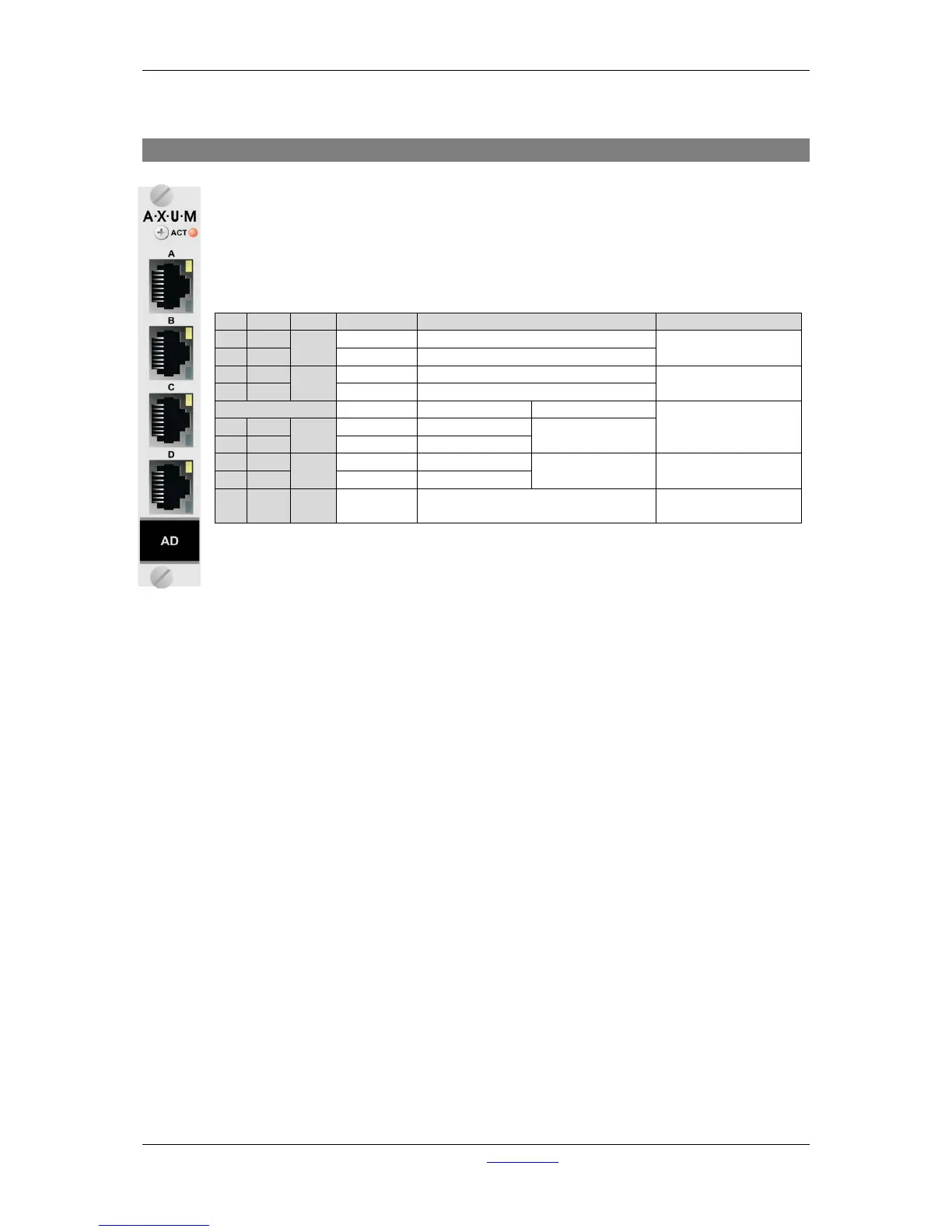
10.2 Line input card
There are four balanced stereo line inputs available on each card.
Each RJ45 connector represents a stereo line input and two GPIO’s which can be
connected to the 19” patch panels with a shielded twisted pair (STP) cable.
For each GPIO you can choose, by way of a hardware jumper on de board, between TTL
Input/output or Photo-MOS relay output see chapter 11.3.1 GPIO TTL/Relay selection. For
software configuration see chapter 9.3 GPIO.
Table 10-2: Line input RJ45 connection
Pin
Con.
Pair
Pin name
Function
Comment
1
1A
1
+Audio 1
Left line input in-phase
Imp. 20kΩ
max. level +26dBu
2
1B
-Audio 1
Left line input out-phase
3
2A
2
+Audio 2
Right line input in-phase
Imp. 20kΩ
max. level +26dBu
6
2B
-Audio 2
Right line input out-phase
If jumper TTL-GPIO If jumper GPO
see chapter 11.3.1
5
3A
3
GPIO1a
GP-Out (TTL)
Photo MOS relay
(max 50V, 200mA)
4
3B
GPIO1b
nGP-In (TTL)
7
4A
4
GPIO2a
GP-Out (TTL)
Photo MOS relay
(max 50V, 200mA)
see chapter 11.3.1
8
4B
GPIO2b
nGP-In (TTL)
S GND S Shield GND
Audio ground and
reference for GP-In

Table of Contents

Related product manuals