EasyManua.ls Logo

D&R AXUM - System Specifications; 12.1 I;O Card Specifications

D&R AXUM
121 pages
Print Icon
To Next Page IconTo Next Page
To Previous Page IconTo Previous Page
Loading...
A·X·U·M User Manual Version 2.5 - 2011-01-28
AXUM from D&R - Phone: +31 294 418014 - E-Mail: info@d-r.nl - 82 -
Relay out (no input available).
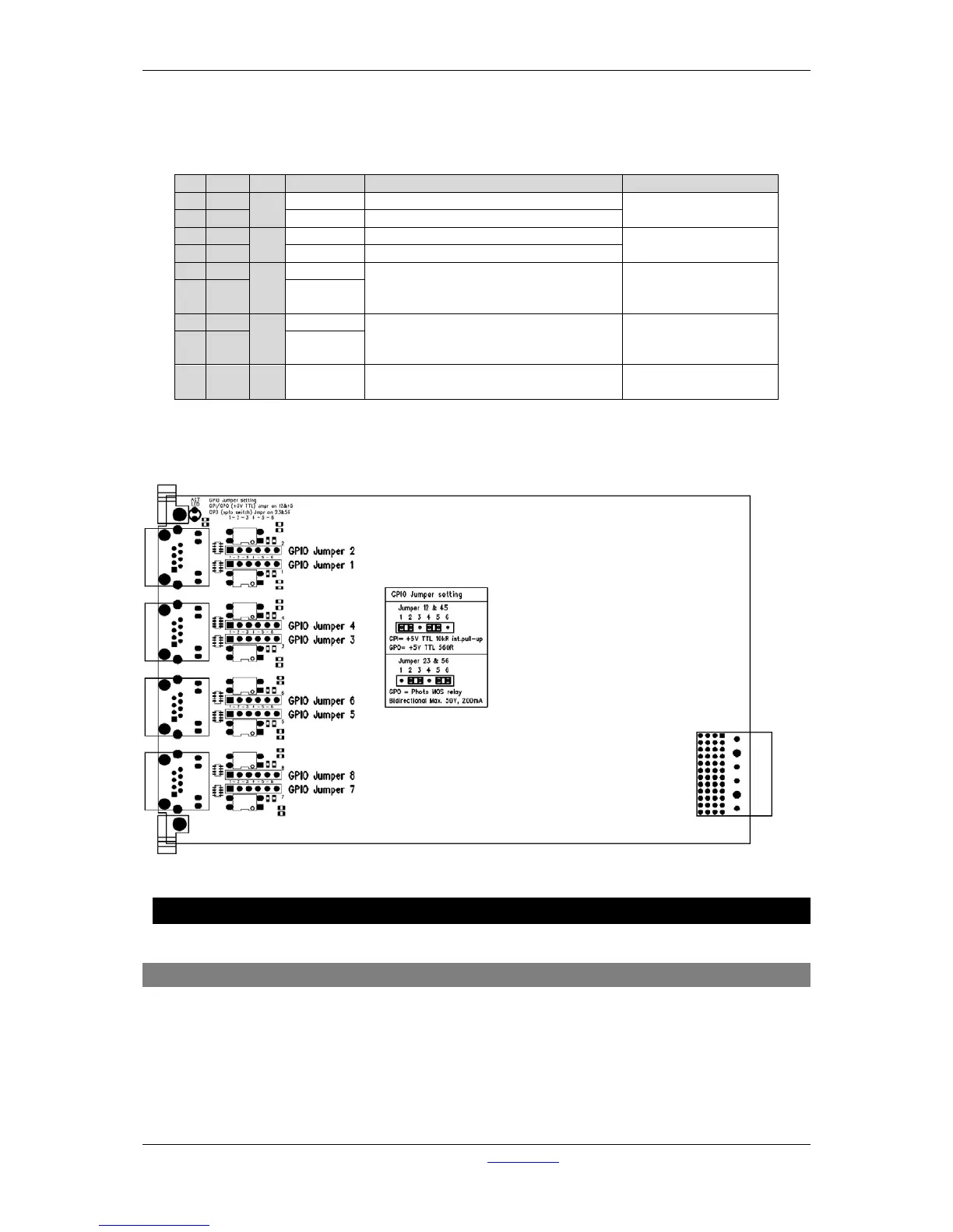
this is selected by GPIO1 jumpers in the place 23 and GPIO2 jumpers in place 56. These
jumpers are located on the I/O cards, close to the RJ45 connectors.
Table 11-6: RJ45 pinning in GPO-Relay mode
The figure shows how the jumper selection on the I/O card looks:
Figure 50: GPIO TTL/Relay jumper selection
12 Specifications AXUM digital audio system
12.1 Input/output cards
Mic inputs : Electronically balanced
: Input impedance 2k Ohm
: Input sensitivity -70dBu up to +20dBu (PAD)
: CMRR MIC inputs: 85dB @ 1kHz, maximum gain
: Phantom is switchable +48 Volts
: Optional is transformer balancing
Pin
Con.
Pair
Pin name
Function
Comment
1
1A
1
+Audio 1
Left audio input or output in-phase
specifications
depends on I/O card
2
1B
-Audio 1
Left audio input or output out-phase
3
2A
2
+Audio 2
Right audio input or output in-phase
specifications
depends on I/O card
6
2B
-Audio 2
Right audio input or output out-phase
5
3A
3
GPIO1a
Relay, connecting a&b
Photo MOS relay
Bidirectional Max.
50V, 200mA
4 3B GPIO1b
7
4A
4
GPIO2a
Relay, connecting a&b
Photo MOS relay
Bidirectional Max.
50V, 200mA
8 4B GPIO2b
S GND S Shield GND
Audio ground and
reference for GP-In

Table of Contents

Related product manuals