FC 300 Operating Instructions
General Specifications
Maximum voltage on input ................................................................................................... 28 V DC
Input resistance, R
i
...................................................................................................... approx. 4 kΩ
Safe stop Terminal 37
4)
:
Terminal 37 is fixed PNP logic
Voltage level .................................................................................................................. 0 -24VDC
Voltage level, logic’0’ PNP .................................................................................................... < 4 V DC
Voltage level, logic’1’ PNP ................................................................................................... >20 V DC
Nominal input current at 24 V ........................................................................................... 50 mA rms
Nominal input current at 20 V ........................................................................................... 60 mA rms
Input capacitance .................................................................................................................. 400 nF
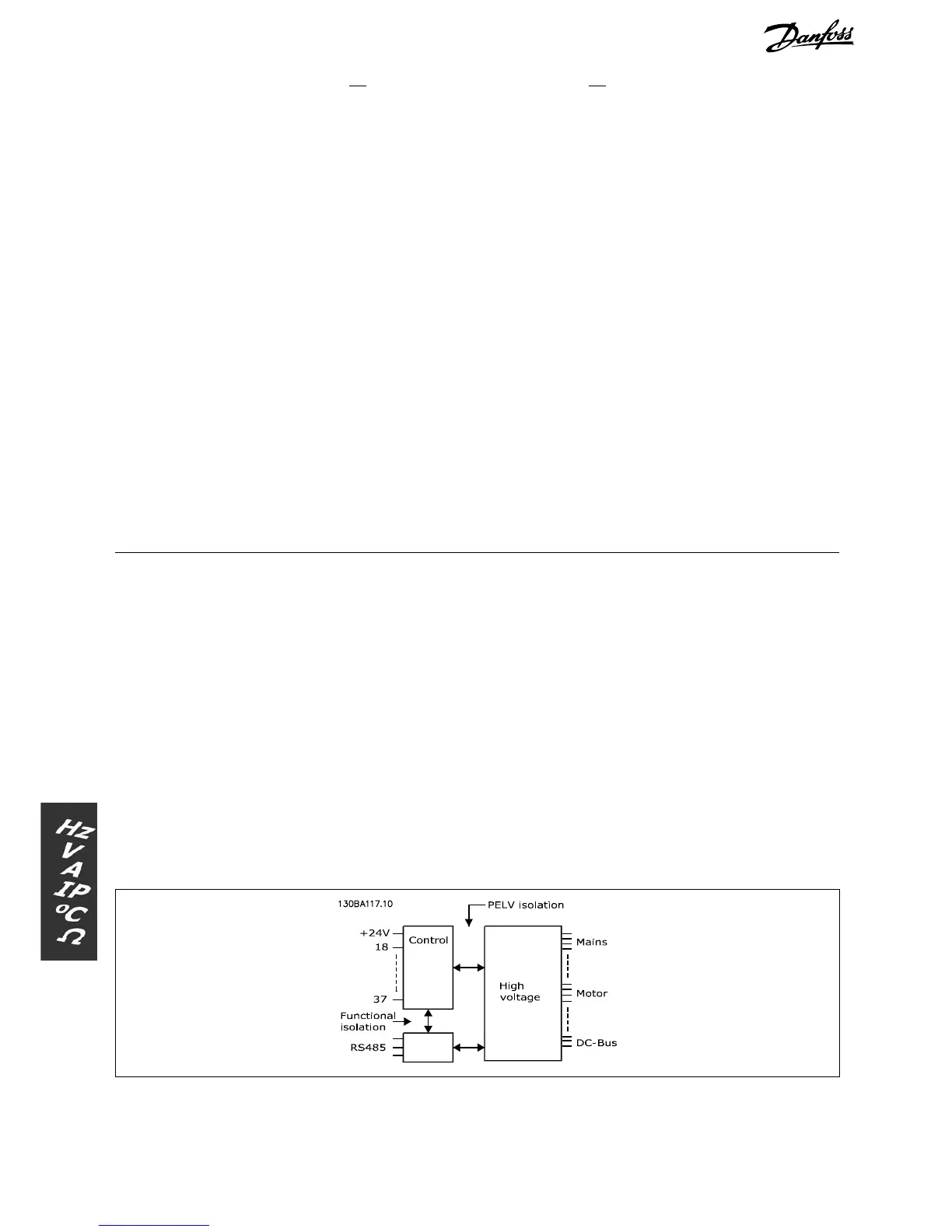
All digital inputs are galvanically isolated from the supply voltage (PELV) and other high-voltage terminals.
1) Terminals 27 and 29 can also b e programme d as output.
2) Exc ept safe stop input Terminal 37.
3) Terminal 37 is only availa ble in FC 302 and FC 301 A1 with Safe Stop. It can only be used a s safe stop input.
Terminal 37 is suitable for category 3 installations a ccording to EN 954-1 (safe stop according to category 0
EN 60204-1) as required by the EU Machinery Directive 98/37/EC. Terminal 37 and the Safe Stop function are
designed in conformance with EN 602 04-1, EN 50178, EN 61800-2, EN 61800-3 , and EN 9 54-1. For correc
t
and safe use of the Safe Stop function follo w the related information and instructions in the Design Guide.
4) FC 302 and FC 301 A1with Safe Stop only.
Analog inputs:
Number of analog inputs ................................................................................................................ 2
Te rminal number ................................................................................................................... 53, 54
Modes ................................................................................................................. Voltage or current
Mode select .......................................................................................... Switch S201 and switch S202
Voltage mode .............................................................................. Switch S201/switch S202 = OFF (U)
Voltage level ........................................................ FC 301: 0 to + 1 0 / FC 302: -10 to +10 V (scaleable)
Input resistance, R
i
.................................................................................................... approx. 10 kΩ
Max. voltage ........................................................................................................................ ± 20 V
Current mode ................................................................................ Switch S201/switch S202 = ON (I)
Current level ............................................................................................... 0/4 to 20 mA (scaleable)
Input resistance, R
i
.................................................................................................... approx. 200 Ω
Max. current ........................................................................................................................ 30 mA
Resolution for analog inputs ......................................................................................... 10 bit (+ sign)
Accuracy of analog inputs ......................................................................... Max. error 0.5% of full scale
Bandwidth ........................................................................................ FC 301: 20 Hz / FC 302: 100 Hz
The analog inputs are galvanically isolated from the supply voltage (PELV) and other
high-voltage terminals.
68
MG.33.A7.02 - VLT is a registered Danfoss trademark
 Loading...


