FC 300 Operating Instructions
How to Install
" Motor Connection
NB!:
Motor cable must be screened/armoured.
If an unscreened/unarmoured cable
is used, some EMC requirements are
not complied with. For mo re information, see
EMC specifications in the VLT AutomationDrive
FC 300 Design Guid e.
See section General Specifications for
correct dimensioning of motor cable
cross-section and length.
• Use a screened/armoured motor cable to
comply with EMC emission specifications. If an
unscreened/unarmoured cable is used, some
EMC requirements are not complied w ith. For
more i n form ation, see EMC specifications in the
VLT AutomationDrive FC 300 Design Guide.
• Keep the motor cable as short as possible to
reduce the noise level and leakage currents.
• Connect the motor cable screen to both the
decoupling plat e of the FC 300 and to the
metal housing of the motor.
• Make the screen connections with the largest
possible surface area (cable clamp). This
is done by using the supplied installation
devices in the FC 300.
• Screening of cables: Avoid installation with
twisted screen ends (pigtails). They spoil the
screening effect at higher frequencies. If it is
necessary to break the screen to install a motor
isolator or motor contactor, the screen must be
continued at the lowest possible HF impedance
.
• If it is necessary to split the screen to
install a motor isolator or motor relay, the
screen must be continued with the lowest
possible HF impedance.
Screening of cables: Avoid installation with
twisted screen ends (pigtails). The y s
poil the
screening effect at higher frequencies. If it is
necessary to break the screen to install a motor
isolator or motor contactor, the
screen must be
continued at the lowest possible HF impedance.
Cable-length and cross-section: The frequency
converter has been te sted with a given length of
cable and a g iven cross-sec
tion of that cable. If the
cross-section is increased, the cab le cap acitanc e -
and thus the leakage current - may incre ase, and
the cable length must be
reduced correspondingly.
Switching frequency: W
hen frequency converters
are used together with LC filters to reduce
the acoustic noise from a motor, the switching
frequency must be set according to the LC
filter instruction in Par. 1 4-01.
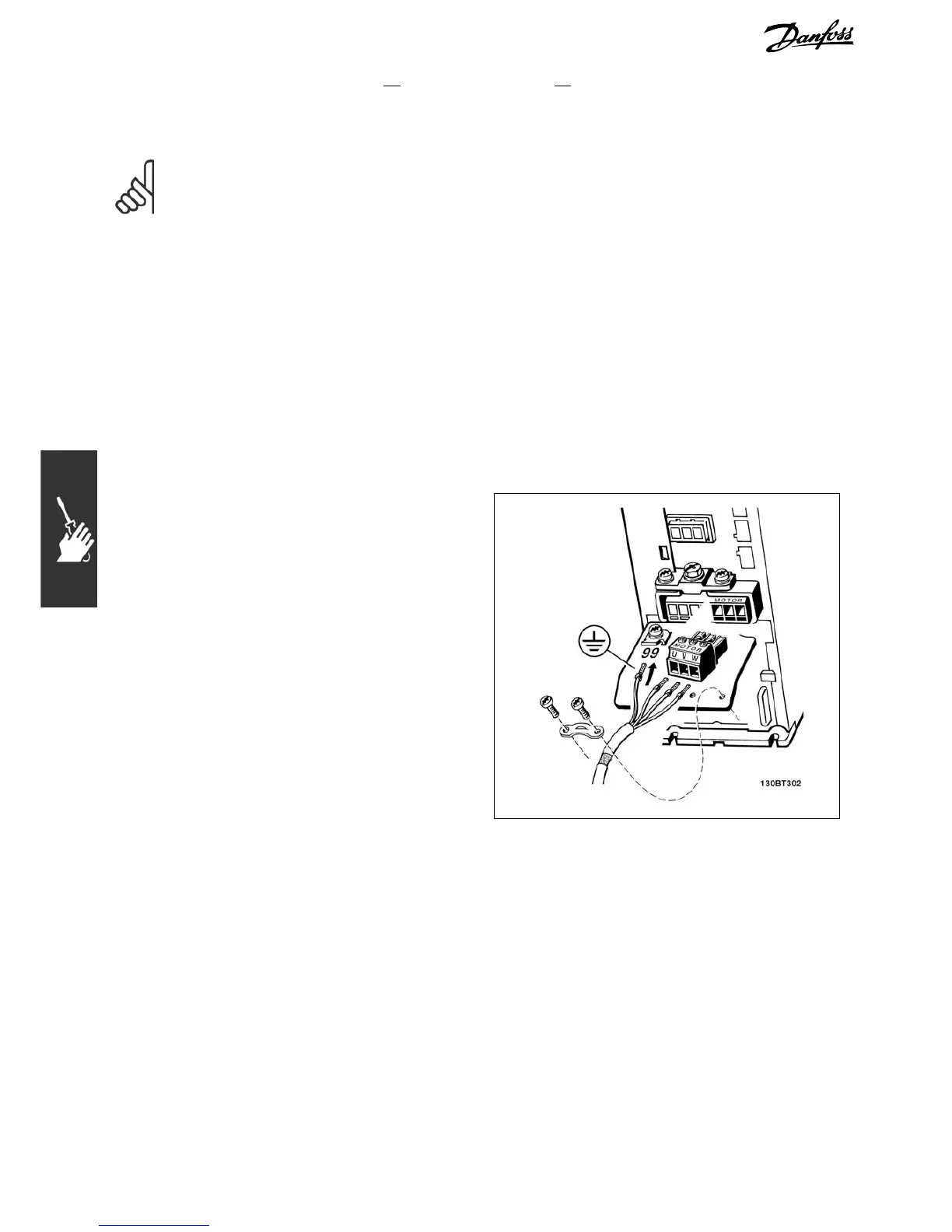
1. Fasten decoupling plate to the bottom of FC 300
with sc rews and washers from the accessory bag.
2. Attach motor cable to terminals 96 (U),
97 (V), 98 (W).
3. Connect to earth connection (terminal
99) on dec oupling plate with sc rew s from
the accessory bag.
4. Insert plug connectors 96 (U), 97 (V), 98
(W) (up to 7.5 kW) and motor ca ble to
terminals labelled MOTOR.
5. Fasten screened cable to decoupling plate with
screws and washers from the acce ssory bag .
Motor connection ≤ 7.5kWIP20(A1,A2andA3enclosures)
20
MG.33.A7.02 - VLT is a registered Danfoss trademark