2.8.6. 5-5* Pulse Input
The pulse input parameters are used to define an appropriate window for the impulse reference
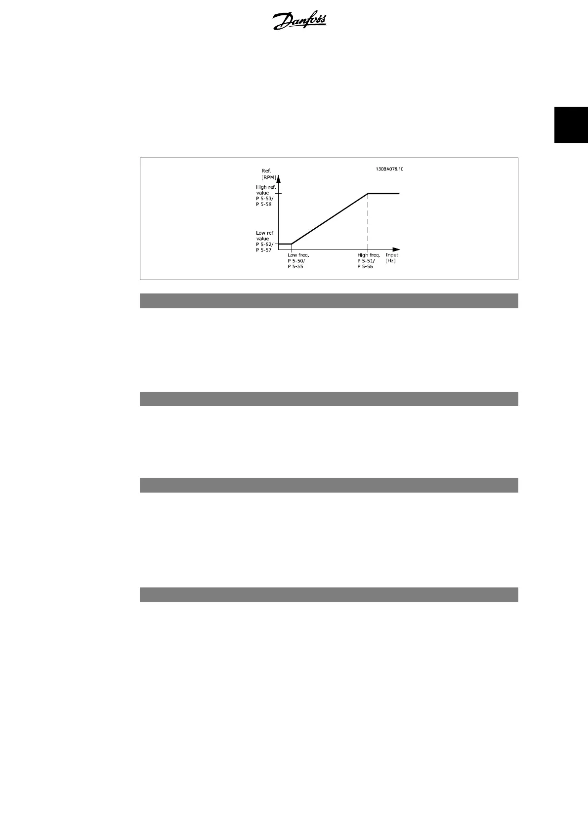
area by configuring the scaling and filter settings for the pulse inputs. Input terminals 29 or 33
act as frequency reference inputs. Set terminal 29 (par. 5-13) or terminal 33 (par. 5-15) to
Pulse
input
[32]. If terminal 29 is used as an input, then set par. 5-01 to
Input
[0].
5-50 Term. 29 Low Frequency
Range: Function:
100 Hz
*
[0 - 110000 Hz] Enter the low frequency limit corresponding to the low motor
shaft speed (i.e. low reference value) in par. 5-52. Refer to the
diagram in this section.
This parameter is available for FC 302 only.
5-51 Term. 29 High Frequency
Range: Function:
100 Hz [0 - 110000 Hz] Enter the high frequency limit corresponding to the high motor
shaft speed (i.e. high reference value) in par. 5-53.
This parameter is available for FC 302 only.
5-52 Term. 29 Low Ref./Feedb. Value
Range: Function:
0.000
*
[-1000000.000 - par.
5-53]
Enter the low reference value limit for the motor shaft speed
[RPM]. This is also the lowest feedback value, see also par. 5-57.
Set terminal 29 to digital output (par. 5-02 =
Output
[1] and par.
5-13 = applicable value).
This parameter is available for FC 302 only.
5-53 Term. 29 High Ref./Feedb. Value
Range: Function:
1500.00
0
*
[Par. 5-52 -
1000000.000]
Enter the high reference value [RPM] for the motor shaft speed
and the high feedback value, see also par.5-58. Select terminal
29 as a digital output (par. 5-02 =
Output
[1] and par. 5-13 =
applicable value).
This parameter is available for FC 302 only.
FC 300 Programming Guide 2. How to Programme
MG.33.M2.02 - VLT
®
is a registered Danfoss trademark
107
2
 Loading...


