2.1.2. The LCD-Display
The LCD-display has back light and a total of 6 alpha-numeric lines. The display lines show the
direction of rotation (arrow), the chosen Set-up as well as the programming Set-up. The display
is divided into 3 sections:
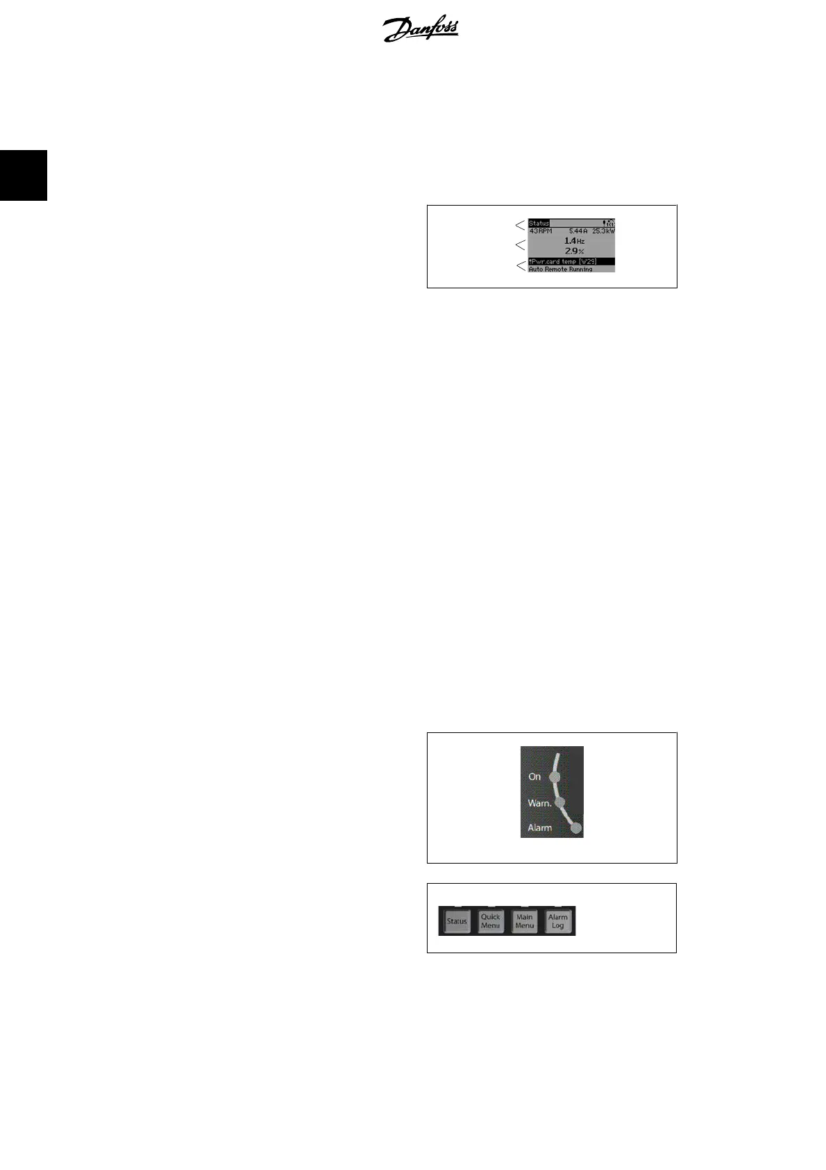
Top section shows up to 2 measurements in
normal operating status.
The top line in the Middle section shows up
to 5 measurements with related unit, regard-
less of status (except in the case of alarm/
warning).
Bottom section always shows the state of
the frequency converter in Status mode.
130BP074.10
Top section
Middle section
Bottom section
The Active Set-up (selected as the Active Set-up in par. 0-10) is shown. When programming an-
other Set-up than the Active Set-up, the number of the programmed Set-up appears to the right.
Display Contrast Adjustment
Press [status] and [▴] for darker display
Press [status] and [▾] for brighter display
Most FC 300 parameter set-ups can be changed immediately via the control panel, unless a pass-
word has been created via par. 0-60
Main Menu Password
or via par. 0-65
Quick Menu
Password
.
Indicator lights (LEDs):
If certain threshold values are exceeded, the alarm and/or warning LED lights up. A status and
alarm text appear on the control panel.
The ON LED is activated when the frequency converter receives mains voltage or via a DC bus
terminal or 24 V external supply. At the same time, the back light is on.
• Green LED/On: Control section is
working.
•Yellow LED/Warn.: Indicates a warn-
ing.
• Flashing Red LED/Alarm: Indicates
an alarm.
130BP040.10
LCP keys
The control keys are divided into functions.
The keys below the display and indicator
lamps are used for parameter Set-up, includ-
ing choice of display indication during normal
operation.
130BP045.1
2. How to Programme FC 300 Programming Guide
12
MG.33.M2.02 - VLT
®
is a registered Danfoss trademark
2

 Loading...


