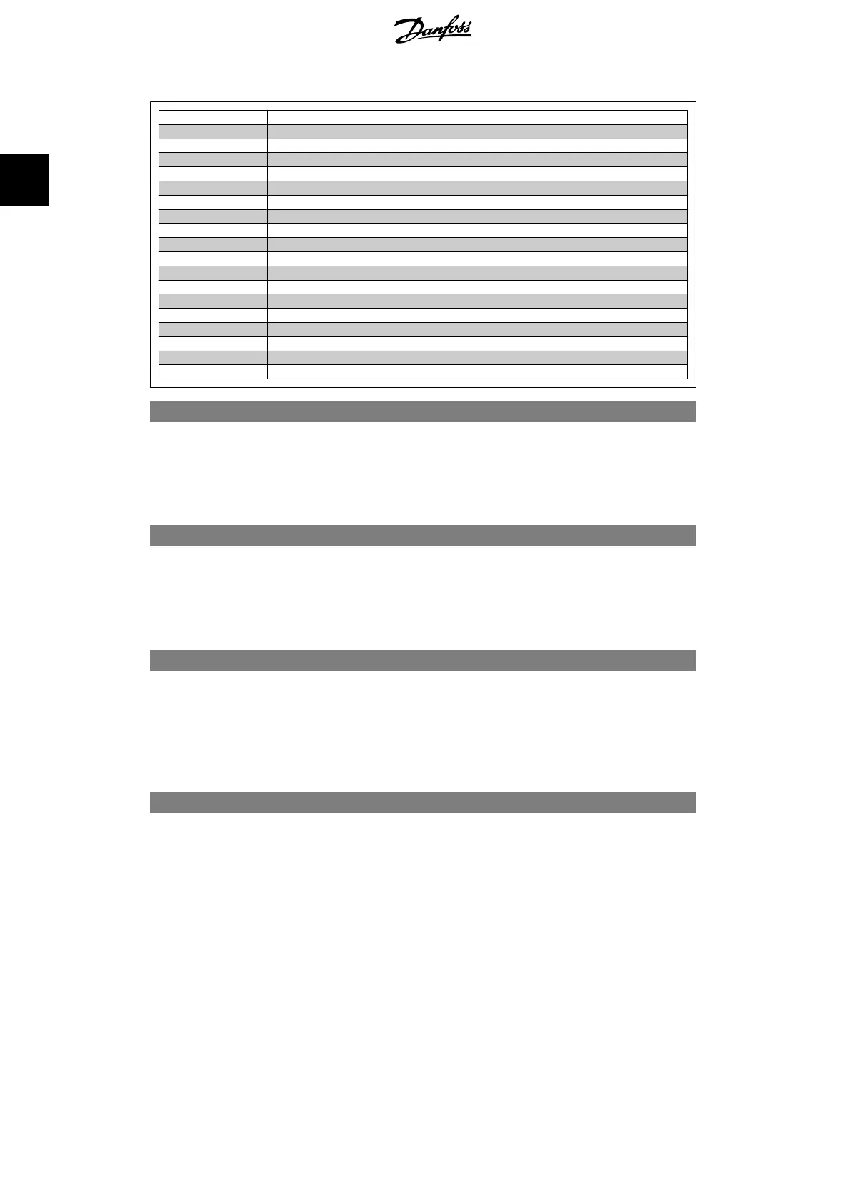
Bit 0 Digital Output Terminal 27
Bit 1 Digital Output Terminal 29
Bit 2 Digital Output Terminal X 30/6
Bit 3 Digital Output Terminal X 30/7
Bit 4 Relay 1 output terminal
Bit 5 Relay 2 output terminal
Bit 6 Option B Relay 1 output terminal
Bit 7 Option B Relay 2 output terminal
Bit 8 Option B Relay 3 output terminal
Bit 9-15 Reserved for future terminals
Bit 16 Option C Relay 1 output terminal
Bit 17 Option C Relay 2 output terminal
Bit 18 Option C Relay 3 output terminal
Bit 19 Option C Relay 4 output terminal
Bit 20 Option C Relay 5 output terminal
Bit 21 Option C Relay 6 output terminal
Bit 22 Option C Relay 7 output terminal
Bit 23 Option C Relay 8 output terminal
Bit 24-31 Reserved for future terminals
5-93 Pulse Output #27 Bus Control
Range: Function:
0%
*
[0.00 - 100.00%] Set the output frequency transferred to the output terminal 27
when the terminal is configured as 'Bus Controlled' in par. 5-60
[45].
5-94 Pulse Output #27 Time-out Preset
Range: Function:
0.00%
*
[0.00 - 100.00%] Set the output frequency transferred to the output terminal 27
when the terminal is configured as 'Bus Ctrl Timeout' in par.
5-60 [48]. And a time-out is detected.
5-95 Pulse Output #29 Bus Control
Range: Function:
0%
*
[0.00 - 100.00%] Set the output frequency transferred to the output terminal 29
when the terminal is configured as 'Bus Controlled' in par. 5-60
[45].
This parameter only applies for FC 302.
5-96 Pulse Output #29 Time-out Preset
Range: Function:
0.00%
*
[0.00 - 100.00%] Set the output frequency transferred to the output terminal 29
when the terminal is configured as 'Bus Ctrl Timeout' in par.
5-60 [48]. And a time-out is detected.
This parameter only applies for FC 302.
2.9. Parameters: Analog In/Out
2.9.1. 6-** Analog In/Out
Parameter group for configuration of the analog input and output.
2. How to Programme FC 300 Programming Guide
112
MG.33.M2.02 - VLT
®
is a registered Danfoss trademark
2

 Loading...


