3-76 Ramp 4 S-ramp Ratio at Accel. End
Range: Function:
50%
*
[1 - 99%] Enter the proportion of the total ramp-up time (par. 3-71) in
which the acceleration torque decreases. The larger the per-
centage value, the greater the jerk compensation achieved, and
thus the lower the torque jerks in the application.
3-77 Ramp 4 S-ramp Ratio at Decel. Start
Range: Function:
50%
*
[1 - 99%] Enter the proportion of the total ramp-down time (par. 3-72)
where the deceleration torque increases. The larger the per-
centage value, the greater the jerk compensation achieved, and
thus the lower the torque jerks in the application.
3-78 Ramp 4 S-ramp Ratio at Decel. End
Range: Function:
50%
*
[1 - 99%] Enter the proportion of the total ramp-down time (par. 3-72)
where the deceleration torque decreases. The larger the per-
centage value, the greater the jerk compensation achieved, and
thus the lower the torque jerks in the application.
2.6.8. 3-8* Other Ramps
Configure parameters for special ramps e.g. Jog or Quick Stop.
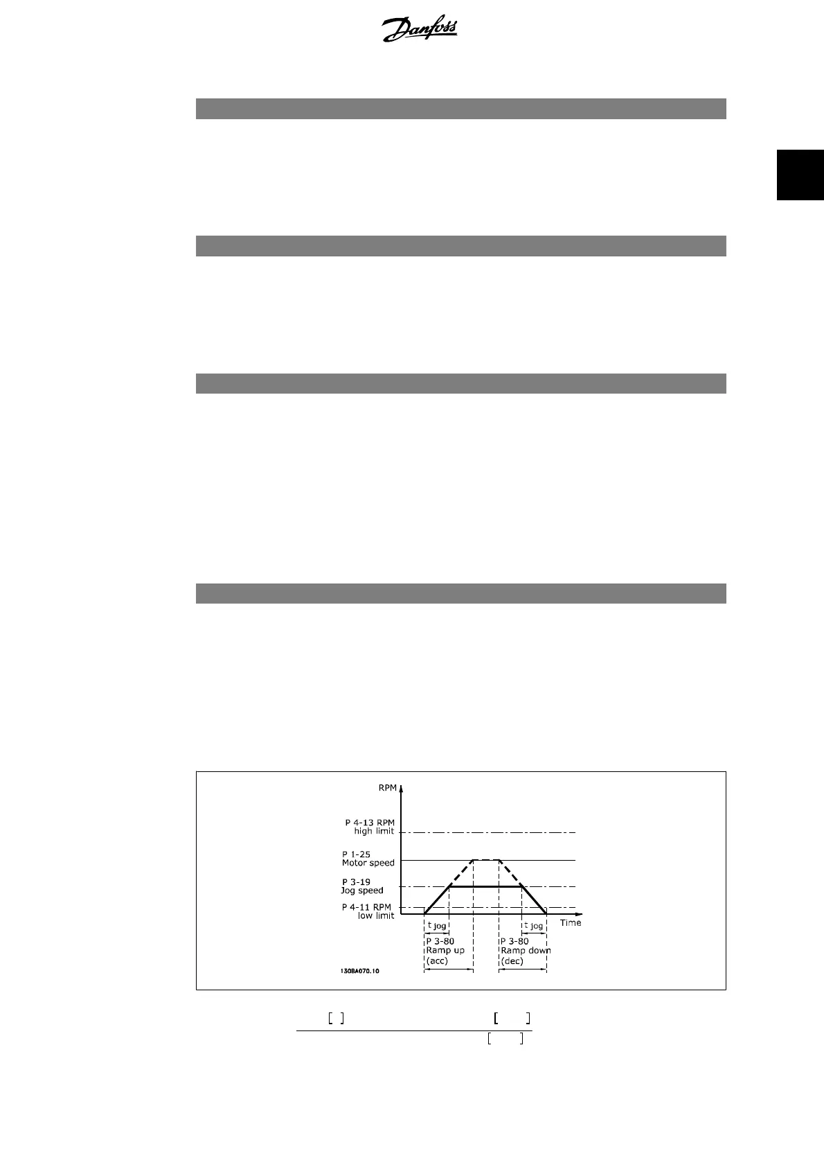
3-80 Jog Ramp Time
Range: Function:
Size re-
lated
[0.01 - 3600.00 s] Enter the jog ramp time, i.e. the acceleration/deceleration time
between 0 RPM and the rated motor frequency n
M,N
(set in par.
1-25
Motor Nominal Speed
). Ensure that the resultant output
current required for the given jog ramp time does not exceed
the current limit in par. 4-18. The jog ramp time starts upon
activation of a jog signal via the control panel, a selected digital
input, or the serial communication port.
Par
.3− 80 =
t
jog
s xn
M
,
N
(
par
.1− 25
)
RPM
Δ
log speed
(
par
.3 − 19
)
RPM
FC 300 Programming Guide 2. How to Programme
MG.33.M2.02 - VLT
®
is a registered Danfoss trademark
83
2

 Loading...


