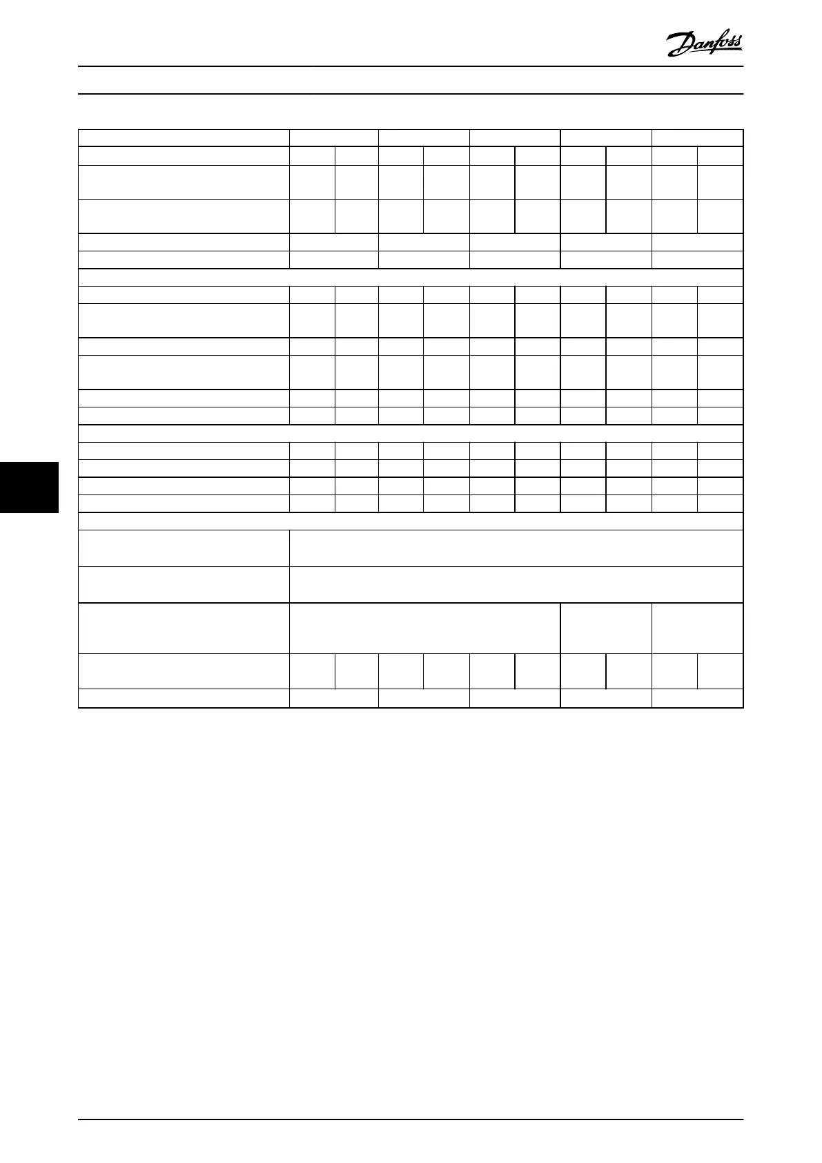
Type designation P30K P37K P45K P55K P75K
High/normal overload
1)
HO NO HO NO HO NO HO NO HO NO
Typical shaft output at 550 V [kW/(hp)] 22
(30)
30
(40)
30
(40)
37
(50)
37
(50)
45
(60)
45
(60)
55
(75)
55
(75)
75
(100)
Typical shaft output at 690 V [kW/(hp)] 30
(40)
37
(50)
37
(50)
45
(60)
45
(60)
55
(75)
55
(75)
75
(100)
75
(100)
90
(125)
Enclosure protection rating IP20 B4 C3 C3 D3h D3h
Enclosure protection rating IP21, IP55 C2 C2 C2 C2 C2
Output current
Continuous (525–550 V) [A] 36.0 43.0 43.0 54.0 54.0 65.0 65.0 87.0 87.0 105
Intermittent (60 s overload) (525–550 V)
[A] 54.0 47.3 64.5 59.4 81.0 71.5 97.5 95.7 130.5 115.5
Continuous (551–690 V) [A] 34.0 41.0 41.0 52.0 52.0 62.0 62.0 83.0 83.0 100
Intermittent (60 s overload) (551–690 V)
[A] 51.0 45.1 61.5 57.2 78.0 68.2 93.0 91.3 124.5 110
Continuous kVA (at 550 V) [kVA] 34.3 41.0 41.0 51.4 51.4 61.9 61.9 82.9 82.9 100
Continuous kVA (at 690 V) [kVA] 40.6 49.0 49.0 62.1 62.1 74.1 74.1 99.2 99.2 119.5
Maximum input current
Continuous (at 550 V) [A] 36.0 49.0 49.0 59.0 59.0 71.0 71.0 87.0 87.0 99.0
Intermittent (60 s overload) (at 550 V) [A] 54.0 53.9 72.0 64.9 87.0 78.1 105.0 95.7 129 108.9
Continuous (at 690 V) [A] 36.0 48.0 48.0 58.0 58.0 70.0 70.0 86.0 – –
Intermittent (60 s overload) (at 690 V) [A] 54.0 52.8 72.0 63.8 87.0 77.0 105 94.6 – –
Additional specications
Maximum cable cross-section
5)
for mains
and motor [mm
2
] ([AWG])
150 (300 MCM)
Maximum cable cross-section
5)
for load
share and brake [mm
2
] ([AWG])
95 (3/0)
Maximum cable cross-section
2),5)
for mains
disconnect [mm
2
] ([AWG])
95, 70, 70
(3/0, 2/0, 2/0)
185, 150, 120
(350 MCM, 300
MCM, 4/0)
–
Estimated power loss
at rated maximum load [W]
3)
600 740 740 900 900 1100 1100 1500 1500 1800
Eciency
4)
0.98 0.98 0.98 0.98 0.98
Table 8.12 B4, C2, C3 Enclosure, Mains Supply 525–690 V IP20/IP21/IP55 – Chassis/NEMA 1/NEMA 12 (FC 302 only), P30K–P75K
For fuse ratings, see chapter 8.7 Fuses and Circuit Breakers.
1) High overload=150% or 160% torque for a duration of 60 s. Normal overload=110% torque for a duration of 60 s.
2) The 3 values for the maximum cable cross-section are for single core, exible wire, and exible wire with sleeve, respectively.
3) Applies to dimensioning of frequency converter cooling. If the switching frequency is higher than the default setting, the power losses may
increase. LCP and typical control card power consumptions are included. For power loss data according to EN 50598-2, refer to
drives.danfoss.com/knowledge-center/energy-eciency-directive/#/
4) Eciency measured at nominal current. For energy eciency class, see chapter 8.4 Ambient Conditions. For part load losses, see
drives.danfoss.com/knowledge-center/energy-eciency-directive/#/.
5) Cable cross-section is regarded for copper cables.
Specications
VLT
®
AutomationDrive FC 301/302
42 Danfoss A/S © 05/2018 All rights reserved. MG33AT02
88